


更换轿车和轻型商用车制动卡钳的说明
请仔细阅读并遵循所有说明。您会在制动钳包中找到相同的说明。请记住在整个产品生命周期中保留它们。如果您出售车辆,请将它们交给新车主。
这些安装说明是标准维修工作的指南,并没有考虑到不同制动系统可能具有的任何特殊性。必须详细遵循车辆和制动系统制造商发布的特定说明。
本文件提供了更换制动钳的说明:
1. 单制动盘卡钳
2. 双盘固定卡钳
3. 带径向安装刹车片的浮动卡钳,2x60/68型。
2. 双盘固定卡钳
3. 带径向安装刹车片的浮动卡钳,2x60/68型。
除非另有说明,本说明书上的所有信息均适用于所有三种类型的制动钳。
更换程序
在开始更换之前,请确定用于更换的备件适合车辆的品牌和型号。
- 拆下车轮。
- 记下所有部分或完全拆卸的组件的位置,以便正确回装。
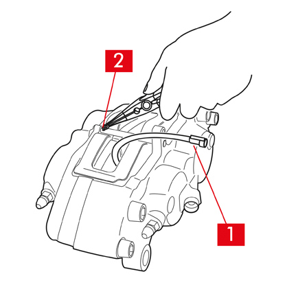
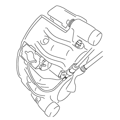
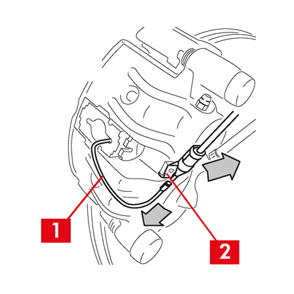
1. 从车辆中的端子上断开磨损指示器电缆(点1)(如果存在),将其与底盘和制动钳上的所有附件松开。
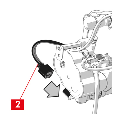
2. 对于装有安全开口销(点2)的型号,请使用钳子将其拆下。
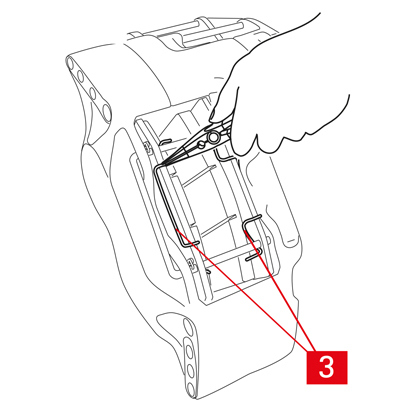
3. 如果是双盘制动卡钳,请使用钳子拆下弹簧(点3)。

4. 使用锤子和销钉起子拔出销钉(点4)。用手完全拉出,确保弹簧(点5)保持在合适的位置。
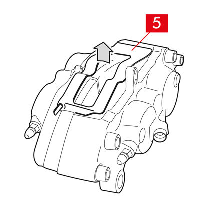
5. 拆下弹簧(点5)。检查液位。打开制动液储液罐盖。
小心!下面描述的活塞回拉的步骤导致储液器中的制动液液位上升。确保制动液的液位不会导致溢出泄漏,因为这会损坏车辆的喷漆部件。
A B 型固定制动钳
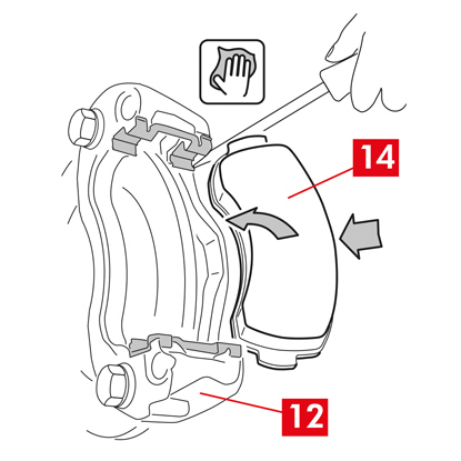
1. 使用牵引器或其他合适的工具稍微拉开活塞,压住刹车片(点6)。
活塞拉回之后,必须将制动钳从制动盘上松开。
2. 如果制动钳的设计允许,请拆下刹车片。否则,请在拆卸制动钳后将其拆下。如果您打算重复使用刹车片,请用记号笔在刹车片上标记制动盘的旋转方向。

C 型浮动制动钳
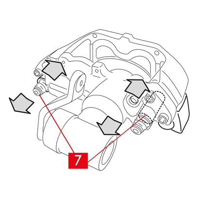
1. 取出刹车片,同时将制动卡钳在导向套上前后滑动(点7)。滑动卡钳体会将刹车片稍微拉离制动盘,从而更容易拆卸。
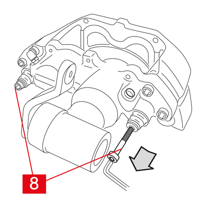
如果制动盘磨损产生的凹痕阻碍刹车片的取出,请拆卸制动卡钳体:
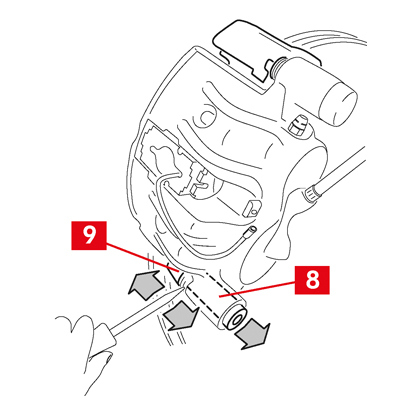
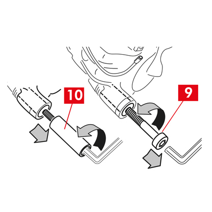
1. 使用扳手拆卸螺丝(点8)

2. 使用螺丝刀将导向衬套从专用座中撬出。
3. 充分取出导向衬套(点7),将其从制动卡钳支架(点9)上拆下。
4. 将制动卡钳体(点10)与卡钳支架(点9)完全分离,并使用S形挂钩将其挂入车辆底盘。
5. 取出刹车片。
6. 如果您打算重复使用刹车片,请用记号笔在刹车片上标记制动盘的旋转方向。
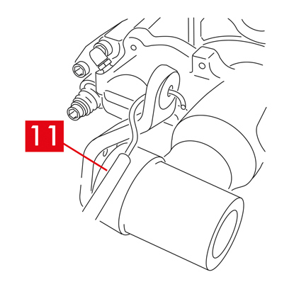
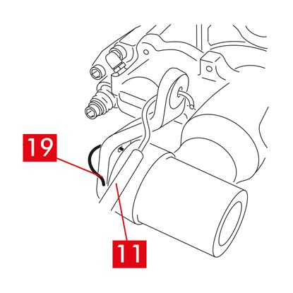
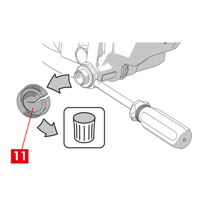
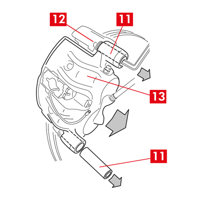
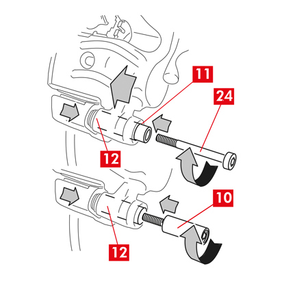
7. 对于后制动卡钳(带驻车机构),断开驻车控制电缆(点11)。
危险!制动液管路必须保持松弛且不拉伸。如果拉伸管路,它们可能会断裂且制动液可能会泄漏。
适用于所有类型的制动钳
1. 关闭制动液储液罐盖。
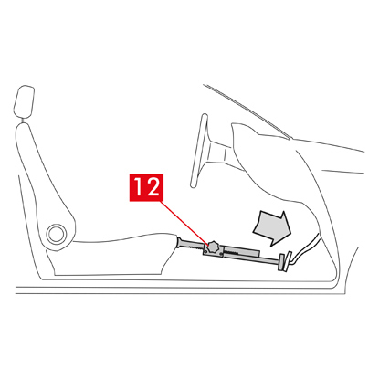
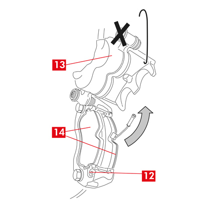
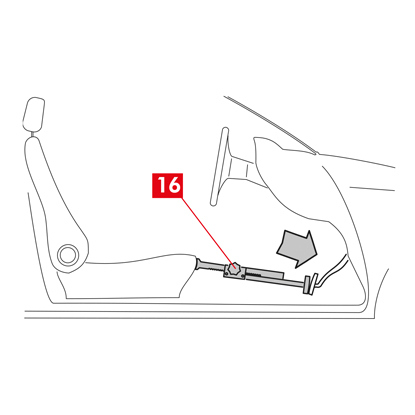
2. 在乘客舱内座椅和制动踏板之间放置一个垫片(点12),以确保踏板在这些操作期间保持踩下状态。
警告! 这样可以关闭制动液压回路,避免制动液泄漏。
小心!在下面描述的所有阶段中,确保制动液不会接触到车辆上可能损坏的部件,尤其是喷漆部件。立即用厨房毛巾擦去意外溅出或泄漏的制动液并用水清洗。
警告! 这样可以关闭制动液压回路,避免制动液泄漏。
小心!在下面描述的所有阶段中,确保制动液不会接触到车辆上可能损坏的部件,尤其是喷漆部件。立即用厨房毛巾擦去意外溅出或泄漏的制动液并用水清洗。
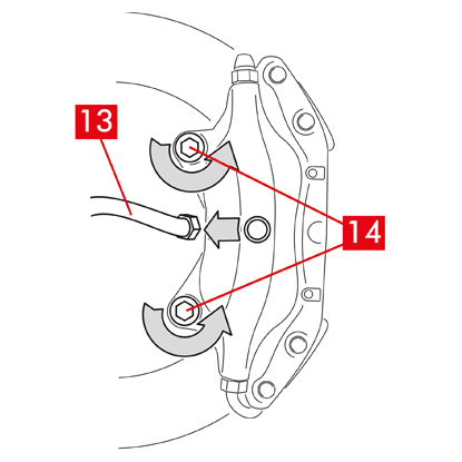
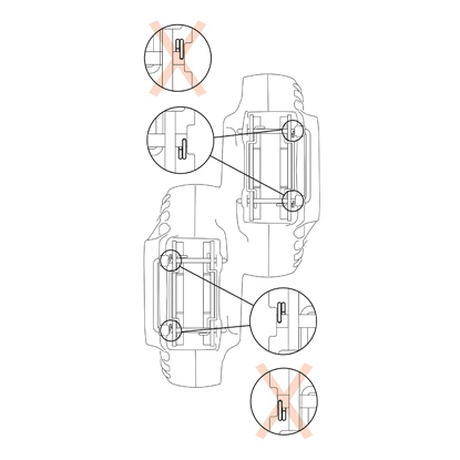
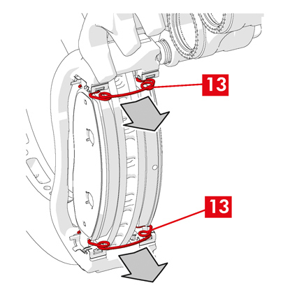
3. 充分松开制动钳上的供给管路(点13),以便能够用手将其完全拧下,但要避免任何制动液泄漏。
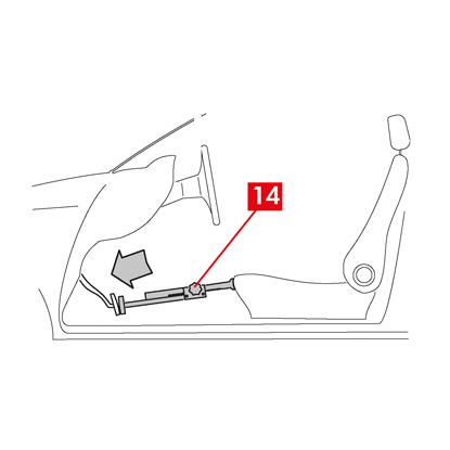
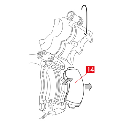
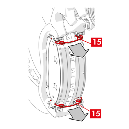
4. 使用开口扳手拧下紧固螺丝(点14),然后从轴上拆下制动卡钳。

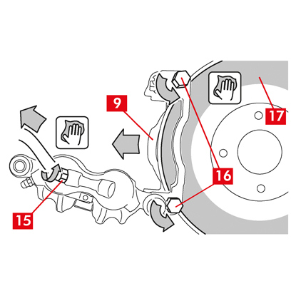
5. 小心!对于双盘制动卡钳,仅拆卸轴紧固螺丝。请勿拆卸将半卡钳连接在一起的螺丝(点15)。
6. 将供应管道(点13)与制动钳完全分离。
7. 立即擦掉泄漏的制动液。
8. 保持供应管道升高,以防止任何意外的液体泄漏。
9. 拉开要更换的卡钳。
9. 拉开要更换的卡钳。
装配程序

1. 将刹车片(点16)插入新制动钳。
警告! 刹车片上印有的箭头必须指向光盘旋转方向。
危险!插入刹车片时摩擦材料必须面向制动盘。
2. 警告!如果制动卡钳的设计允许,也可以在安装卡钳后插入刹车片,即在“拧紧紧固螺丝”步骤之后。
危险! 确保摩擦表面没有沾上油脂,否则必须用砂纸清除所有油脂痕迹。
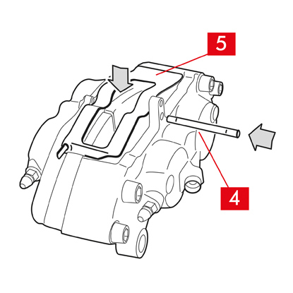
3. 将弹簧(点5)和销(点4)重新插入制动卡钳和刹车片的专用安座中。必须使用锤子和销钉起子将销钉完全打入。
安装弹簧时请注意方向。
4. 检查弹簧是否正确定位。
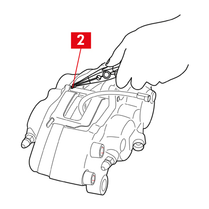
5. 对于配备安全开口销(点2)的型号,使用钳子重新定位它们。
6. 检查开口销是否正确定位。
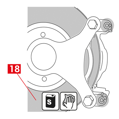
7. 使用脱脂产品(例如溶剂 SE 47)清洁制动盘(点18)上的制动表面(点17)。
8. 将新制动卡钳放置在轴上,将制动盘(点18)插入刹车片之间。
9. 使用开口扳手拧紧紧固螺丝(点14),并采用车辆制造商推荐的扭矩拧紧。
或者,使用以下推荐的拧紧扭矩作为参考:
| 螺丝类型 | M12x1,25 | M12x1,5 | M14x1,5 |
| 锁紧扭力 | 115 Nm | 125 Nm | 180 Nm |
10. 将磨损指示器电缆(如有)重新连接到车辆中的终端以及底盘和制动钳上的任何附件上。

11. 重新连接制动液供给管路(点13)。
12. 拆下之前放置在乘客舱内的垫片,从而松开制动器踏板并允许回路重新打开。
13. 对于C型后制动卡钳(带驻车机构),重新连接驻车控制电缆(点11)。
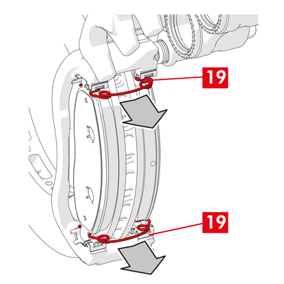
14. 拆下控制杆锁定销(点19)。
15. 在车内拉起驻车制动器。重复该过程几次,直到制动机构杆的行程重新达到最小值。
16. 打开制动液储液罐盖。
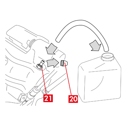
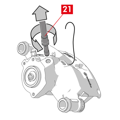
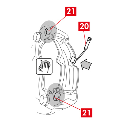
17. 取下保护帽(点20)并将透明管连接到制动钳上的放气塞(点21),其末端应放置在容器中以收集所有液体。
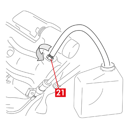
18. 打开放气塞(点21)。
19. 反复踩下车辆制动踏板,直至制动液开始从放气塞溢出。
20. 踩下踏板,关闭放气塞。松开踏板,等待几秒钟,然后重复该过程,直到没有任何气泡的液体溢出,直到制动踏板恢复正常的阻力和行程。
21. 使用表中规定的扭矩拧紧放气塞:
| 放气塞 | M6x1 | M6x1 | M6x1 | M6x1 |
| 锁紧扭力 | 5÷7 Nm | 7÷10 Nm | 17÷20 Nm | 18÷22 Nm |
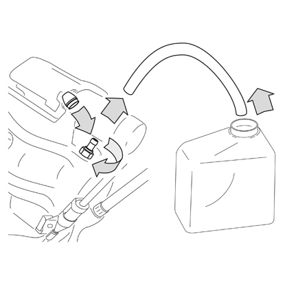
22. 拆下透明管并将保护帽重新放置在放气塞上。
23. 对任何其他放气塞重复放气过程。
24. 放气过程结束后,使用适当的工具(例如伸缩器)将制动钳中的活塞完全拉回,然后按照制造商的建议加满液位。
25. 关闭制动液储液罐盖。
26. 发动机运转时,用力踩下车辆制动踏板,检查制动钳是否有液体泄漏或回路中是否存在异常压力损失,并且后制动灯是否亮起。
危险!如果液体从制动钳泄漏,请重复本文档中列出的所有步骤,以查明原因并解决问题。
27. 如果卡钳带有内置驻车制动器,请将驻车制动电缆端子连接至制动卡钳上的相应位置。反复拉动并松开驾驶舱驻车制动器。
28. 重新装上车轮。
29. 如果刹车片是新的,请将其磨合;按照备用垫提供的说明进行操作。
以下是更换制动钳的说明:
带中央弹簧的浮动制动钳
带有2个或4个侧弹簧和残余扭矩减少弹簧的浮动制动钳。
除非另有说明,本说明书上的所有信息均适用于两种类型的制动卡钳。
更换程序
在开始更换之前,请确定用于更换的备件适合车辆的品牌和型号。
- 拆下车轮
- 记下所有部分或完全拆卸的组件的位置,以便正确回装。
1. 从车辆中的端子上断开磨损指示器(点1)(如有),从将其固定到卡钳的垫片(点2)以及底盘上可能的附件上松开。

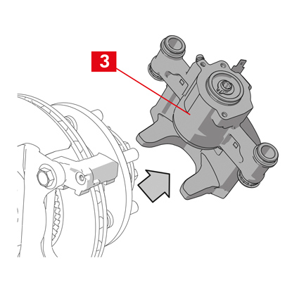
2. 从导向衬套上拆下保护帽(点3)。
3. 如果保护帽有唇缘(点4),则用手指拉动唇缘(点4),将帽拉出。
4. 如果帽是硬塑料制成的(点5),请用螺丝刀撬开。取下帽会损坏它。
警告! 请勿重复使用拆卸后的硬塑料帽。
小心! 拆卸的导向衬套必须是允许制动卡钳体转动而不导致制动液供给管路拉伸的导向衬套。
警告! 导向衬套有两种类型:
- 带独立螺丝
- 带内置螺丝
- 带内置螺丝

5. 使用扳手松开并完全拆下螺丝(点6)或内置导向衬套(点7)。
警告! 如果制动卡钳上粘有刹车片,请使用螺丝刀将其拆下。
危险! 打开制动卡钳体可能会导致残余扭矩减小弹簧弹开。
6. 如果是非内置导向衬套(点8),则将导向衬套从卡钳支架(点9)中拉出,并用螺丝刀将其从底座中撬出。
7. 当更换带有悬架和板簧的后轮上的卡钳时,必须拆下两个导向衬套(点11),以将制动卡钳体(点10)与制动卡钳支架(点9)完全分离。

8. 将制动卡钳(点10)绕另一个导向衬套扭转,将其拉离卡钳支架(点9),直至刹车片从卡钳支架中脱出。使用专门的支撑将制动卡钳体固定到车辆底盘上。

9. 在不造成任何损坏的情况下拆下刹车片(点11)和弹簧(点12),以便您可以将它们重新组装到新制动卡钳上。
10. 使用记号笔在制动盘上标记制动盘的旋转方向,以避免错误地回装制动盘。
11. 如果它们仍位于原位,请拆下残余扭矩减小弹簧(点13)。
12. 在乘客舱内座椅和制动踏板之间放置一个垫片(点14),以确保踏板在这些操作期间保持踩下状态。
警告! 这样可以关闭制动液压回路,避免制动液泄漏。
小心! 在下面描述的所有阶段中,确保制动液不会接触到车辆上可能损坏的部件,尤其是喷漆部件。立即用厨房毛巾擦去意外溅出或泄漏的制动液,并用水清洗。
警告! 这样可以关闭制动液压回路,避免制动液泄漏。
小心! 在下面描述的所有阶段中,确保制动液不会接触到车辆上可能损坏的部件,尤其是喷漆部件。立即用厨房毛巾擦去意外溅出或泄漏的制动液,并用水清洗。
13. 充分松开卡钳上的供给管路(点15),以便能够用手将其完全拧下,因为这样可以避免可能的制动液泄漏。
14. 使用开口扳手拧松固定螺栓(点16),然后从轮毂支架上拆下卡钳支架(点9)。
15. 将供给管路(点15)与制动卡钳完全分离。
16. 立即擦掉泄漏的制动液。
17. 保持供应管线升高以防止液体泄漏。
18. 如果制动卡钳带有内置驻车制动器,请将驻车制动拉绳从卡钳上的座上断开。
19. 拉开要更换的卡钳。
20. 使用脱脂产品(例如 Solvent SE47)清洁制动盘上的制动表面(点17)。
制动卡钳安装程序
小心! 在将供应管线连接到新制动卡钳上之前,请勿从新制动卡钳上的流体入口孔拆下保护帽。
安装新制动卡钳之前,使用提供的润滑脂润滑衬套和防尘盖。
警告! EUH210 - 可根据要求提供安全数据表。
警告! EUH208 - 含有 N-烷基化苯并三唑。可能会引起过敏反应。
1. 从衬套上取下保护帽(如有)。
2. 松开螺丝或带有内置螺丝的导向衬套。
3. 如果是单独的螺丝,请将螺丝完全取出。
4. 将制动卡钳脱离卡钳支架。
警告! 为避免损坏防尘盖,请从防尘盖侧面拉出衬套。
5. 取下盖子。
6. 使用适当的产品(例如湿布)彻底清洁所有要安装的部件、衬套座和盖座。
7. 清洁轮毂支架上的安装面。

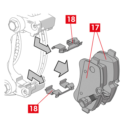
8. 将新的制动卡钳支架(点18)插入制动盘中,将其定位。
9. 插入并接近两个固定螺栓(点19和20)。
10. 使用车辆制造商推荐的扭矩拧紧制动盘入口侧(点19)(前进档)的固定螺栓。
11. 使用车辆制造商推荐的扭矩拧紧第二固定螺栓 20(在制动盘出口侧)。
使用以下推荐拧紧扭矩作为参考:
| 螺丝类型 | 锁紧扭力 |
| M12x1,25 | 115 Nm |
| M12x1,5 | 125 Nm |
| M14x1,5 | 180 Nm |
| M16x1,5 | 210 Nm |
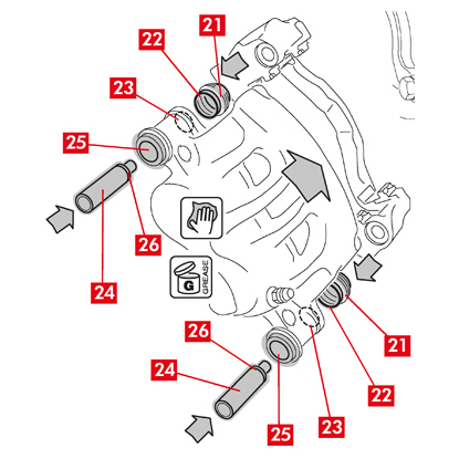
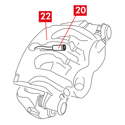
12. 均匀地润滑盖板的整个内表面(点21)以及与制动卡钳的接触面(点22)。
13. 将盖(点21)插入制动卡钳上的座(点23)中。
小心! 用手指检查盖是否已插入并正确固定在卡钳中。
14. 在卡钳中的衬套(点24)及其座(点25)的外表面涂上润滑脂,然后将衬套从与盖相对的一侧插入卡钳中。
15. 推动衬套(点24),直到盖(点21)安装到其底座(点26)中。

16. 清除多余的油脂。
17. 将制动卡钳安装到卡钳支架上,穿过并拧紧制动盘出口侧的螺丝或内置衬套(前进档)。
18. 通过围绕导向衬套扭转卡钳主体(点27),将其拉离卡钳支架(点18),直至刹车片进入卡钳支架。使用专门的支撑将制动卡钳体固定到车辆底盘上。
小心! 请勿将导向衬套座用作连接点。
安装刹车片
1. 如果需要,将侧弹簧(点12)安装到卡钳支架中,施加适当的压力以将其牢固地固定。

2. 对于带有四个弹簧的卡钳,安装弹簧时务必使翅片面向卡钳支架的外侧。
小心! 遵守正确的安装方向。
警告! 如果有刹车片带有粘性面,则必须安装新刹车片;请按照备用刹车片提供的说明进行操作。
小心! 带有磨损指示器的刹车片必须安装回其拆卸前的原始位置。
小心! 遵守正确的安装方向。
警告! 如果有刹车片带有粘性面,则必须安装新刹车片;请按照备用刹车片提供的说明进行操作。
小心! 带有磨损指示器的刹车片必须安装回其拆卸前的原始位置。

3. 将刹车片(点11)重新插入卡钳支架(点18);对于B型卡钳,使用螺丝刀撬开侧弹簧(点12)。
警告! 刹车片上印有的箭头必须指向光盘旋转方向。
危险! 插入刹车片时摩擦材料必须面向制动盘。
警告! 刹车片上印有的箭头必须指向光盘旋转方向。
危险! 插入刹车片时摩擦材料必须面向制动盘。
4. 将磨损指示器电缆(点1)穿过专用管道,如下所示:
对于A型卡钳 - 在弹簧中(点28)。
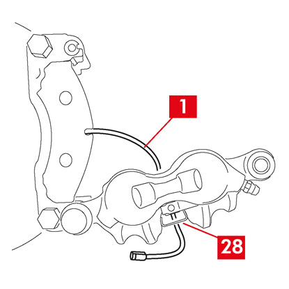
对于B型卡钳 - 在卡钳体内(点27)。

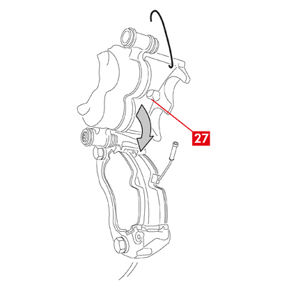
4. 围绕旋紧的导向衬套扭转卡钳(点27),小心地闭合卡钳。如果有刹车片带有粘合面,请注意在完成制动卡钳主体安装之前不要在卡钳和刹车片之间形成接触。
小心! 小心地闭合卡钳,确保衬套上的保护帽不会因撞击卡钳支架而损坏。
小心! 小心地闭合卡钳,确保衬套上的保护帽不会因撞击卡钳支架而损坏。
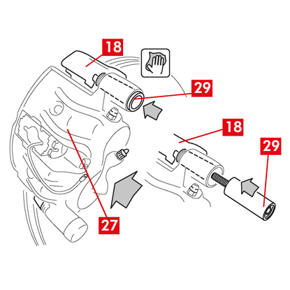
5. 将卡钳(点27)移向制动卡钳支架(点18)。
6. 将导向衬套(点29)重新插入卡钳支架座中。
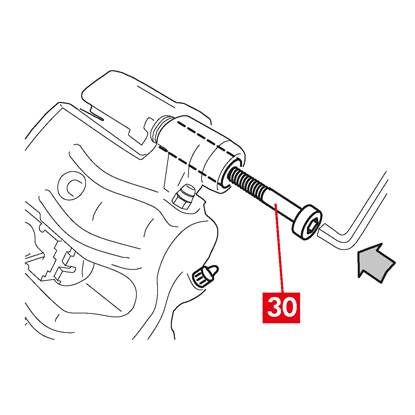
7. 如果有新螺丝(点30),则插入并拧紧。

8. 当更换带有悬架和板簧的后轮上的制动卡钳时,必须将卡钳(点27)重新定位在卡钳支架(点18)上,然后重新插入两个导向衬套(点29)并插入并拧紧两个新螺丝(点30),如果有。
9. 如果尚未拧紧,请拧紧导向衬套紧固螺丝或阀盘入口侧(前进档)上的内置导向衬套。接下来,以相同的扭矩拧紧其他螺丝或内置导向衬套。
10. 按下表规定的拧紧扭矩拧紧:
| 类型 | 锁紧扭力 | |
| 固定螺丝 | (M8 – CH6) | 32 ÷ 36 Nm |
| 带内置螺丝的导向套 | (M8 – CH6) | 32 ÷ 36 Nm |
| 带内置螺丝的导向套 | (M10 – CH8) | 65 ÷ 75 Nm |
危险! 遵守所描述的拧紧顺序;否则可能会影响制动卡钳的正常运行。
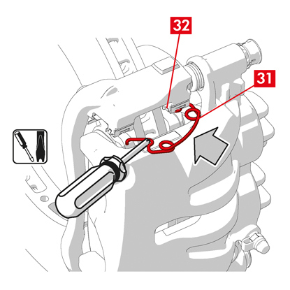
11. 如果是残余扭矩减小弹簧(点31),则将弹簧钩在刹车片背板(点32)下方,并借助空心螺丝刀将背板的下侧钩在另一个刹车片上。
危险! 弹簧安装不正确可能会导致其弹开。
小心! 遵守正确的安装方向。
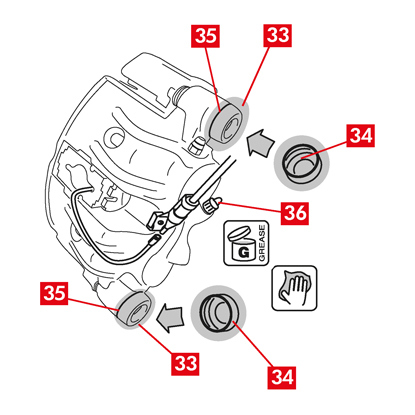
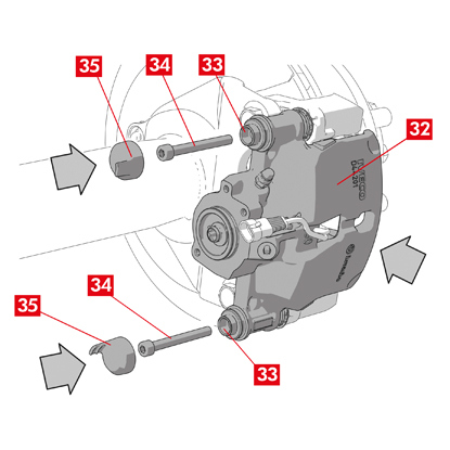
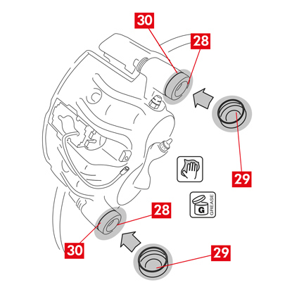
12. 仔细清洁零件(点33),确保它们固定到位并安装新的保护帽(点34),用备件套件中提供的润滑脂润滑其内表面和卡钳安座。
13. 转动保护帽(点34),使其完全粘附在阀座上(点35)。
14. 将磨损指示器(如有)重新连接到车辆中的端子,轻轻按压将其固定到卡钳上的垫片上,并将所有附件固定在底盘上。
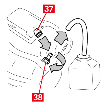
15. 从制动液入口孔(点36)拆下保护帽。
16. 重新连接制动液供给管路。
17. 拆下之前放置在乘客舱内的垫片,从而松开制动器踏板并允许液压回路重新打开。
18. 打开制动液储液罐盖。
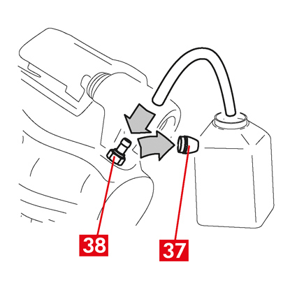
19. 取下保护帽(点37)并将透明管连接到制动钳上的放气塞(点38),其末端应放置在容器中以收集所有液体。
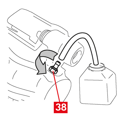
20. 打开放气塞(点38)。
21. 反复踩下车辆制动踏板,直至制动液开始从放气塞溢出。
22. 踩下踏板,关闭放气塞。松开踏板,等待几秒钟,然后重复该过程,直到没有任何气泡的液体溢出,直到制动踏板恢复正常的阻力和行程。
23. 使用表中规定的扭矩拧紧放气塞:
| 放气塞 | M6x1 | M8x1,25 | M10x1 | M12x1 |
| 锁紧扭力 | 5÷7 Nm | 7÷10 Nm | 17÷20 Nm | 18÷22 Nm |
24. 拆下透明管并将保护帽重新放置在放气塞上。
25. 对任何其他放气塞重复放气过程。
26. 放气过程结束后,使用适当的工具(例如伸缩器)将制动钳中的活塞完全拉回,然后按照制造商的建议加满液位。
27. 关闭制动液储液罐盖。
28. 发动机运转时,用力踩下车辆制动踏板,检查制动钳是否有液体泄漏或回路中是否存在异常压力损失,并且后制动灯是否亮起。
危险! 如果液体从制动钳泄漏,请重复本文档中列出的所有步骤,以查明原因并解决问题。
29. 如果卡钳带有内置驻车制动器,请将驻车制动电缆端子连接至制动卡钳上的相应位置。
30. 反复拉动并松开驾驶舱驻车制动器。
31. 重新装上车轮。
32. 如果刹车片是新的,请将其磨合;按照备用垫提供的说明进行操作。
以下是更换带有内置电动驻车机构的商用车浮动制动卡钳(ECS53 和 ECS60 型)的组件的说明:
1. 执行器单元
2. 刹车片
3. 制动卡钳体(不含刹车片和卡钳支架)
4. 制动卡钳支架
2. 刹车片
3. 制动卡钳体(不含刹车片和卡钳支架)
4. 制动卡钳支架
警告! 更换包装中包含的备件之前请阅读本文档。仅执行更换包装中包含的一个或多个备件所需的步骤。
更换程序
在开始更换之前,请确定用于更换的备件适合车辆的品牌和型号。
警告! 如果发生电气故障,请拆卸执行器单元并将活塞拉回,用合适的扳手顺时针旋转扭矩螺丝。
- 记下所有部分或完全拆卸的组件的位置,以便正确回装。

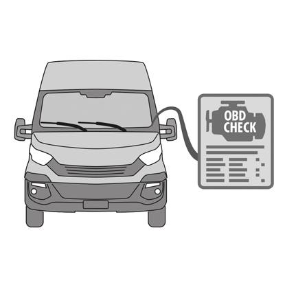
1. 将诊断工具(车载诊断 - OBD)连接到车辆,并将其置于车辆制造商所述的维护模式程序中。
小心! 确保备件与车辆软件兼容。
2. 拆下车轮。
3. 将执行器单元电源线从电缆接头上松开。
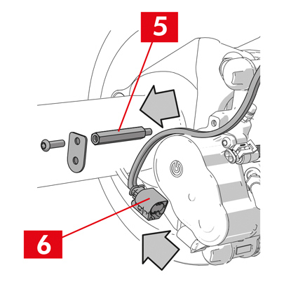
4. 对于 ECS60 型制动卡钳,松开并拆下电缆密封套(点5)。
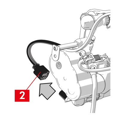
5. 从执行器单元上断开电源线(点6)。
警告! 连接器可以配备有安全闩锁。
警告! 连接器可以配备有安全闩锁。
拆卸执行器单元
警告! 仅当有单独的备件可用时方可继续拆卸执行器单元。
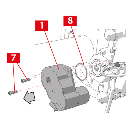
1. 松开执行器单元(点1)上的紧固螺丝(点7)。
2. 拆下执行器单元(点1)。
3. 拆下密封件(点8)。
拆卸刹车片
小心! 不要损坏您打算重复使用的任何组件。
危险! 请勿拉伸制动液供给管路。
危险! 请勿拉伸制动液供给管路。
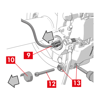
1. 从车辆中的端子上断开磨损指示器(点9)(如有),从将其固定到卡钳的垫片以及底盘上的任何附件上松开。
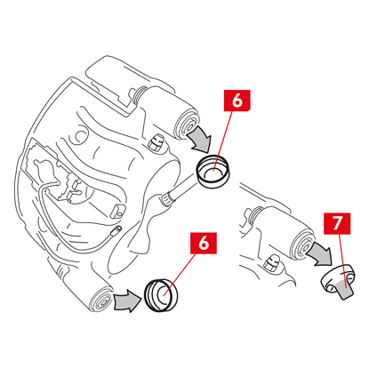
2. 从辅助衬套(向前驱动旋转盘出口侧)拆下保护帽(点10)。
3. 如果帽是硬塑料制成的(点11),请用螺丝刀撬开。取下帽会损坏它。
警告! 请勿重复使用拆卸后的硬塑料帽。
4. 松开并拆下辅助螺丝(点12)。
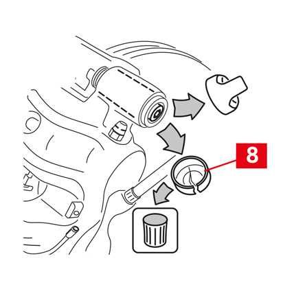
5. 对于 ECS60 型卡钳,使用螺丝刀将衬套从凹槽中撬出,将其从卡钳支架上松开。

6. 从主衬套(向前驱动旋转盘入口侧)拆下保护帽(点14)。
7. 完全松开主螺丝(点15)并将其拆下。
警告! 使用螺丝刀将导向衬套从凹槽中撬出。
8. 充分取出主导向衬套(点16),将其从卡钳支架上松开。

9. 将制动卡钳体(点3)拉离卡钳支架(点4),注意不要导致制动液供给管路拉伸。
10. 使用专门的支撑将制动卡钳体固定到车辆底盘上。
小心! 请勿将衬套座用作连接点
11. 在不造成任何损坏的情况下拆下刹车片(点17)和弹簧(点18),以便您可以将它们重新组装到新制动卡钳上。
12. 如果它们仍位于原位,请拆下残余扭矩减小弹簧(点19)。
警告! 为了正确重新安装相同的制动盘,请用记号笔在制动盘上标记一些箭头(如没有),以指示制动盘的旋转方向。
拆卸制动卡钳体

1. 在乘客舱内座椅和制动踏板之间放置一个垫片(点20),以确保踏板在这些操作期间保持踩下状态。
警告! 这样可以关闭制动液压回路,避免制动液泄漏。
小心! 在下面描述的所有阶段中,确保制动液不会接触到车辆上可能损坏的部件,尤其是喷漆部件。立即用厨房毛巾擦去意外溅出或泄漏的制动液,并用水清洗。
2. 充分松开卡钳上的供给管路(点21),以便能够用手将其完全拧下,因为这样可以避免可能的制动液泄漏。
3. 将供给管路(点21)与制动卡钳完全分离。
4. 立即擦掉泄漏的制动液。
5. 保持供应管线升高以防止液体泄漏。
6. 拉开制动卡钳(点3)。
拆卸卡钳支架

小心! 拆卸时,请保持制动卡钳支架就位,以免意外掉落。
1. 松开紧固螺丝(点22)。
2. 从轮毂支架上拆下制动卡钳支架(点4)。
装配程序

重新组装新的备用部件。
1. 使用适当的产品(例如湿布)彻底清洁所有要安装的部件(无论是新的还是以前拆下的)、衬套座和弹簧座。
危险! 确保组件完好无损,如果损坏则用新组件更换。
2. 清洁轮毂支架上的安装面(点23)。
3. 使用脱脂产品(例如 Solvent SE47)清洁制动盘上的制动表面(点24)。
安装制动卡钳支架

1. 将新的卡钳支架(点25)放置在轮毂支架上。
2. 插入紧固螺丝(点26)并按照车辆制造商推荐的扭矩拧紧。
安装刹车片和制动卡钳
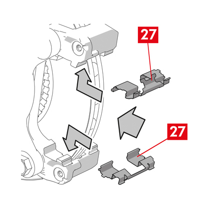
1. 重新插入弹簧(点27),将它们以正确的方式放置在其位置上。
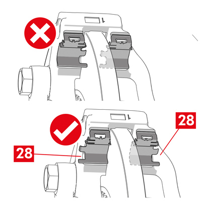
2. 对于带有四个弹簧的 ECS52 型制动卡钳,安装弹簧时始终使翅片(点28)面向制动卡钳支架的外侧。
警告! 如果有刹车片带有粘性面,则必须安装新刹车片;请按照备用刹车片提供的说明进行操作。
小心! 带有磨损指示器的刹车片必须安装回其拆卸前的原始位置。
危险! 插入刹车片时摩擦材料必须面向制动盘。

3. 将刹车片(点29)重新插入制动卡钳支架(点25);使用螺丝刀撬开侧弹簧(点27)。

4. 如果是残余扭矩减小弹簧(点30),则将弹簧钩在刹车片背板(点31)下方,并借助空心螺丝刀将背板的下侧钩在另一个刹车片上。
危险! 弹簧安装不正确可能会导致其弹开。
危险! 弹簧安装不正确可能会导致其弹开。

小心! 遵守正确的安装方向。
小心! 如果制动卡钳体是新的,请不要从新卡钳上的流体入口孔上拆下保护帽,直到将供应管线连接到其上。
6. 通过将制动卡钳体(点32)插入制动盘来定位卡钳体,使导向衬套与卡钳支架上的孔重合。
小心! 请勿损坏帽。
7. 将导向衬套(点33)推入制动卡钳支架上的相应位置。
8. 插入螺丝并拧紧螺丝(点34),拧紧扭矩为 32 ÷ 36 Nm。
9. 放置帽(点35)。
小心! 在拆下保护帽之前,将供给点保持在尽可能高的位置,确保制动卡钳内的制动液不会泄漏。
10. 将磨损指示器电缆(如有)重新连接到车辆中的端子,轻压将其固定到卡钳上的垫片(如有)上,并将所有附件固定在底盘上。
连接制动液供给管路

1. 从制动液入口孔拆下保护帽(点36)。
2. 重新连接制动液供给管路(点21)。
3. 拆下之前放置在乘客舱内的垫片,从而松开制动器踏板并允许回路重新打开。

4. 从放气塞(点38)上拆下保护帽(点37)。
5. 将透明管连接到制动卡钳上的放气塞(点38),其末端应放置在容器中以收集所有液体。

6. 打开放气塞(点38)。
7. 反复踩下车辆制动踏板,直至制动液开始从放气塞溢出。
8. 踩下踏板,关闭放气塞。松开踏板,等待几秒钟,然后重复该过程,直到没有任何气泡的液体溢出,直到制动踏板恢复正常的阻力和行程。
9. 使用下表中规定的扭矩拧紧放气塞(点38):
| 排放类型 | M10x1 |
| 锁紧扭力 | 12÷16 Nm |
10. 取下透明管。
11. 对任何其他放气塞重复放气过程。
12. 重新放置保护盖(点37)。
13. 放气过程结束后,使用适当的工具(例如伸缩器)将制动钳中的活塞完全拉回,然后按照制造商的建议加满液位。
14. 发动机运转时,用力踩下车辆制动踏板,检查制动钳是否有液体泄漏或回路中是否存在异常压力损失,并且后制动灯是否亮起。
危险! 如果液体从制动钳泄漏,请重复本文档中列出的所有步骤,以查明原因并解决问题。

安装执行器单元
警告! 执行器单元在供货时可能已经安装到制动卡钳体上。
重新组装新的备用部件。
- 重新组装之前,请先清洁之前拆下的所有组件。
小心! 始终使用带有螺纹锁固剂的新螺丝。务必安装新密封件。
危险! 确保组件完好无损,如果损坏则用新组件更换

1. 清洁制动卡钳和执行器单元上的接触面。
2. 清除螺纹螺丝座上的所有螺纹锁固剂残留物。
3. 使用提供的润滑脂清洁并润滑密封件(点39)。
4. 使用所提供的润滑脂润滑执行器单元联轴器的内径。
警告! EUH210 - 可根据要求提供安全数据表。
警告! EUH208 - 含有 N-烷基化苯并三唑。可能会引起过敏反应。

5. 将密封件(点39)放置在制动卡钳上的安座(点40)中。
6. 将执行器单元(点41)安装到制动卡钳体上的扭矩螺丝(点42)上。
7. 转动执行器单元(点41),使紧固螺丝(点44)的孔(点43)与其原始安装位置重合。
小心! 将执行器单元安装到制动卡钳体上时,避免挤压密封件(点39)。
8. 插入紧固螺丝(点44)并以 7 ÷ 10 Nm 的紧固扭矩拧紧。

9. 取下保护帽(点45)(如果有),然后连接电源线(点6)。
10. 拧紧先前拆下的电缆密封套(点5)。
11. 将执行器单元供电电缆(点6)固定至电缆密封套(点5)。
最后阶段
1. 重新装上车轮。
2. 执行重置程序(装配检查)。
3. 如有必要,请按照车辆制造商的规定重置计数器(重置内部计数器)。
4. 如果车辆制造商要求,请在刹车片中行驶。
5. 断开诊断设备。(车载诊断 - OBD)。
以下是更换带有2个或4个侧弹簧和残余扭矩减少弹簧的浮动制动卡钳的卡钳体的说明。
在只更换紧固螺丝时,仅参考相关零件。

更换程序
在开始更换之前,请确定用于更换的备件适合车辆的品牌和型号。
- 记下所有部分或完全拆卸的组件的位置,以便正确回装。
- 拆下车轮。
适用于ECS制动卡钳
警告! 如果发生电气故障,请拆卸执行器单元(点5)并将活塞拉回,用合适的扳手顺时针旋转扭矩螺丝
1. 将诊断工具(车载诊断 - OBD)连接到车辆,并将其置于车辆制造商所述的维护模式程序中。
小心! 如果不进行此操作,则无法使用收缩器或其他合适的工具将活塞拉回。
小心! 确保备件与车辆软件兼容。
2. 从执行器单元上断开电源线(点2)。
警告! 连接器可以配备有安全闩锁。
适用于所有类型的制动钳

1. 对于带有驻车制动器的卡钳,从卡钳上拆下控制电缆(点3)。

2. 从车辆中的端子上断开磨损指示器(点4)(如有),从将其固定到卡钳的垫片(点5)以及底盘上的任何附件上松开。
3. 从导向衬套上拆下保护帽(点6)。
4. 如果保护帽有唇缘(点7),则用手指拉动唇缘(点7),将帽拉出。
5. 如果帽是硬塑料制成的(点8),请用螺丝刀撬开。取下帽会损坏它。
警告! 请勿重复使用拆卸后的硬塑料帽。
小心! 拆卸的导向衬套必须是允许制动卡钳体转动而不导致制动液供给管路拉伸的导向衬套。
警告! 导向衬套有两种类型:带独立螺丝、带内置螺丝。
警告! 请勿重复使用拆卸后的硬塑料帽。
小心! 拆卸的导向衬套必须是允许制动卡钳体转动而不导致制动液供给管路拉伸的导向衬套。
警告! 导向衬套有两种类型:带独立螺丝、带内置螺丝。
6. 使用扳手松开并完全拆下螺丝(点9)或内置导向衬套(点10)。

7. 如果是非内置导向衬套(点11),则将导向衬套从卡钳支架(点12)中拉出,并用螺丝刀将其从底座中撬出。
8. 当更换带有悬架和板簧的后轮上的卡钳时,必须拆下两个导向衬套11,以将制动卡钳体(点13)与卡钳支架(点12)完全分离。
警告! 如果制动卡钳上粘有刹车片,请使用螺丝刀将其拆下,并注意不要损坏制动卡钳的橡胶部件。
危险! 打开制动钳体可能会导致残余扭矩减小弹簧弹开。
9. 将制动卡钳(点13)绕另一个导向衬套扭转,将其拉离卡钳支架(点12),直至刹车片(点14)从卡钳支架中脱出。使用专门的支撑将制动卡钳体固定到车辆底盘上。请勿将衬套座用作连接点。
11. 取下刹车片(点14),不要造成任何损坏。
12. 使用记号笔在制动盘上标记制动盘的旋转方向,以避免错误地回装制动盘。
14. 如果它们仍位于原位,请拆下残余扭矩减小弹簧(点15)。
15.在乘客舱内座椅和制动踏板之间放置一个垫片(点16),以确保踏板在这些操作期间保持踩下状态。
警告! 这样可以关闭制动液压回路,避免制动液泄漏。
小心! 在下面描述的所有阶段中,确保制动液不会接触到车辆上可能损坏的部件,尤其是喷漆部件。立即用厨房毛巾擦去意外溅出或泄漏的制动液,并用水清洗。
小心! 在下面描述的所有阶段中,确保制动液不会接触到车辆上可能损坏的部件,尤其是喷漆部件。立即用厨房毛巾擦去意外溅出或泄漏的制动液,并用水清洗。

16. 充分松开卡钳上的供给管路(点17),以便能够用手将其完全拧下,因为这样可以避免可能的制动液泄漏。
17. 完全松开并拆下螺丝(点9)或内置导向衬套(点10)。
18. 如果是非内置导向衬套(点11),则将导向衬套从卡钳支架(点12)中拉出,并用螺丝刀将其从底座中撬出。
19. 将制动卡钳体(点13)拉离卡钳支架(点12),注意不要导致制动液供给管路拉伸。
20. 将供给管路(点17)与制动卡钳完全分离。
21. 立即擦掉泄漏的制动液。
22. 保持供应管线抬高,以防止制动液泄漏。
23. 拉开要更换的卡钳。
24. 如果制动卡钳带有内置驻车制动器,请将驻车制动拉绳从卡钳上的座上断开。
25. 使用脱脂产品(例如 Solvent SE47)清洁制动盘上的制动表面。
安装刹车片
小心! 如果有刹车片带有粘性面,则必须安装新刹车片;请按照备用刹车片提供的说明进行操作。

1. 检查弹簧是否正确定位。如果制动卡钳带有四个弹簧,请确保翅片始终面向卡钳支架的外侧。
小心! 弹簧位置不正确可能会导致受伤。
2. 将刹车片(点14)插入制动卡钳支架(点12)。使用螺丝刀按压侧面弹簧。
警告! 刹车片上印有的箭头必须指向光盘旋转方向。
危险! 插入刹车片时摩擦材料必须面向制动盘。
小心! 带有磨损指示器的刹车片必须安装回其拆卸前的原始位置。
警告! 刹车片上印有的箭头必须指向光盘旋转方向。
危险! 插入刹车片时摩擦材料必须面向制动盘。
小心! 带有磨损指示器的刹车片必须安装回其拆卸前的原始位置。
3. 如果存在磨损指示器端子(点20),请将其连接到活塞对面的刹车片上,必要时进行更换。
小心! 安装磨损指示器端子时,确保最突出的部分面向刹车片的摩擦表面。
小心! 安装磨损指示器端子时,确保最突出的部分面向刹车片的摩擦表面。
安装制动卡钳
小心! 对于带驻车制动器的卡钳:当卡钳体从制动盘上拆卸下来和/或缺少刹车片时,请勿通过液压方式或使用控制杆移动活塞,因为这可能会损坏弹簧和/或导致制动液泄漏。
1. 在卡钳支架上,用湿布擦拭卡钳体(导向座)的安装区域(点21)。
小心! 请勿使用可能损坏保护帽的产品,例如硝基四氯乙烯稀释剂、汽油等。
2. 清洁并均匀地润滑帽的整个内表面、导向衬套的外表面及其在卡钳体内的座。

3. 定位新制动卡钳(点22),将两个导向衬套之一(点10)设置在卡钳支架(点12)的底座中。
小心! 在管道最终连接之前,请勿拆下制动液入口孔的保护盖。
4. 如果是非内置导向衬套(点11),请安装并拧紧新螺丝(点23)。
5. 围绕固定的导向衬套扭转卡钳(点22),小心地闭合卡钳。
小心! 小心地闭合卡钳,确保衬套上的保护帽不会因撞击卡钳支架而损坏。如有必要,请更换保护帽。
警告! 如果有刹车片带有粘合面,请注意在完成卡钳主体安装之前不要在主体和刹车片之间形成接触。
6. 将磨损指示器探针(点20)穿过卡钳上的专用孔(点22)。
7. 将另一个导向衬套(点10)重新插入卡钳支架座(点12)。
8. 如果是非内置导向衬套(点11),请安装并拧紧新螺丝(点24)。
小心! 当用悬架和板簧更换后轮上的制动卡钳支架时,必须将卡钳重新定位在卡钳支架上,然后重新插入两个导向衬套并插入并拧紧两个新螺丝。

9. 拧紧制动盘入口侧(前进档)的导向衬套紧固螺丝或内置导向衬套(点24)。接下来,以相同的扭矩拧紧另一个螺丝或内置导向衬套(点25)。
10. 按下表规定的拧紧扭矩拧紧:
| 类型 | 锁紧扭力 | |
| 固定螺丝 | (M8 – CH6) | 32 ÷ 36 Nm |
| 带内置螺丝的导向套 | (M8 – CH6) | 32 ÷ 36 Nm |
| 带内置螺丝的导向套 | (M10 – CH8) | 65 ÷ 75 Nm |
危险! 遵守所描述的拧紧顺序;否则可能会影响制动卡钳的正常运行。

11. 如果是残余扭矩减小弹簧(点26),则将弹簧钩在刹车片背板(点27)下方,并借助空心螺丝刀将背板的下侧钩在另一个刹车片上。
危险! 弹簧安装不正确可能会导致其弹开。
小心! 遵守正确的安装方向。
12. 仔细清洁零件(点28),确保其固定到位并安装新的保护帽(点29),用备件套件中提供的润滑脂润滑其内表面和卡钳安座。
警告! EUH210 - 可根据要求提供安全数据表。
警告! EUH208 - 含有 N-烷基化苯并三唑。可能会引起过敏反应。
警告! EUH208 - 含有 N-烷基化苯并三唑。可能会引起过敏反应。
13. 转动保护帽(点29),使其完全粘附在阀座上(点30)。
14. 将磨损指示器(如有)重新连接到车辆中的端子,轻轻按压将其固定到卡钳上的垫片上,并将所有附件固定在底盘上。
15. 拆下制动液入口孔的保护盖。
16. 重新连接制动液供给管路。
17. 拆下之前放置在乘客舱内的垫片,从而松开制动器踏板并允许回路重新打开。
适用于带驻车制动器的卡钳
小心! 在将活塞与刹车片组装之前,请确保制动卡钳支架、刹车片和制动盘都已存在。
- 使用杠杆将活塞与刹车片组装起来。
小心! 仅当活塞距刹车片小于1毫米时才允许进行液压操作。
适用于所有类型的制动钳
1. 将透明管连接到制动卡钳上的放气塞(点31),其末端应放置在容器中以收集所有液体。
2. 打开放气塞(点31)。
3. 反复踩下车辆制动踏板,直至制动液开始从放气塞溢出。
4. 踩下踏板,关闭放气塞。松开踏板,等待几秒钟,然后重复该过程,直到没有任何气泡的液体溢出,直到制动踏板恢复正常的阻力和行程。
5. 使用表中规定的扭矩拧紧放气塞(点31):
| 放气塞 | M6x1 | M8x1,25 | M10x1 | M12x1 |
| 锁紧扭力 | 5÷7 Nm | 7÷10 Nm | 17÷20 Nm | 18÷22 Nm |

6. 取下透明管。
7. 对任何其他放气塞重复放气过程。
8. 放气过程结束后,使用适当的工具(例如伸缩器)将制动钳中的活塞完全拉回,然后按照制造商的建议加满液位。
9. 关闭制动液储液罐盖。
10. 发动机运转时,用力踩下车辆制动踏板,检查制动钳是否有液体泄漏或回路中是否存在异常压力损失,并且后制动灯是否亮起。
危险! 如果液体从制动钳泄漏,请重复本文档中列出的所有步骤,以查明原因并解决问题。
适用于带驻车制动器的卡钳
- 将磨损指示器(如有)重新连接到车辆中的端子,轻轻按压将其固定到卡钳上的垫片上,并将所有附件固定在底盘上。
- 恢复控制拉绳的正确张力。
- 重复操作驾驶室中的驻车制动杆,直至重新建立正常行程。
适用于ECS制动卡钳
1. 取下保护帽(如果有)并连接电源线(点2)。
2. 执行重置程序(装配检查)。
3. 如有必要,请按照车辆制造商的规定重置计数器(重置内部计数器)。

4. 如果车辆制造商要求,请在刹车片中行驶。
5. 断开诊断设备(车载诊断 - OBD)。
适用于所有类型的制动钳
1. 重新装上车轮。
2. 如果刹车片是新的,请将其磨合;按照备用垫提供的说明进行操作。
2. 如果刹车片是新的,请将其磨合;按照备用垫提供的说明进行操作。
保修限制
本保修涵盖货物交付后两年内发生的所有合规的缺陷。消费者必须在发现缺陷之日起两个月内向卖方报告合规的缺陷,但不影响自交付货物起二十六个月内采取旨在纠正缺陷行动的时效期限。根据《消费者权益保护法》第 130 条的规定,如果货物存在合格缺陷,用户有权要求修理或更换货物,或要求适当降价或终止合同。
本保修构成与本产品相关的唯一保修,并取代任何其他口头和书面保修。
如果出现缺陷,用户需要:
- 在六十天内以书面形式通知制造商和经销商;同时,用户应提供在产品上或在退回的部件上发现的缺陷描述,以及原始用户的购买证明,其中应注明产品和购买日期(无论是零售购买还是由经销商出售作为产品安装的一部分);
- 通过分销链将被认为有缺陷的产品发送至 Brembo S.p.A. 位于 via Brembo 25 -24035 Curno (BG) - Italy 的总部。
保修不适用于以下情况:
- 由于不正确使用、事故、火灾、化学腐蚀、用于预定用途之外的用途、非法使用、使用与规定型号不同的型号、不正确安装、违反制造商指示的安装或未按照制造商提供的说明对产品进行维护而部分或全部造成的产品损坏;
- 与舒适性、噪音、振动或恶劣的骑行特性有关的投诉。
该产品是针对Brembo目录和/或Brembo产品经销商指定的特定型号和用途而设计和生产的,两者均可在Brembo网站 (www.brembo.com) 上查阅。产品的使用应遵守安装产品的车辆所在州和/或国家的现行法律,包括但不限于遵守《公路法》的规定,并在获得州和/或国家要求的任何授权/批准、许可或执照后使用。
对于在欧盟成员国境内销售的产品,这些保修限制符合1985年7月25日欧盟理事会 85/374/EEC指令的规定。
对于在美国境内销售的产品,这些保修限制遵循所有适用的联邦或州法律。
一般和安全信息
该 Brembo 产品的设计符合所有适用的安全标准。产品的用必须与其设计和制造的特定用途相符。将产品用于任何其他目的,或任何修改或篡改产品可能影响产品的性能,并可能导致产品不安全。
此类修改或不当使用将使受限的保修失效,并可能使使用产品的个人对他人造成的人身伤害或财产损失承担责任。
在这些说明中,“危险!“警告是指如果不遵守,很可能导致严重伤害甚至死亡的程序。“注意”表示如果不遵守,可能会导致物理损坏的程序,而“警告!”是指如果不遵守,可能会导致车辆损坏的程序。
危险!
在开始更换之前,请确定备件适合车辆的品牌和型号。本产品对于安装该产品的车辆的安全操作至关重要,只能由经过培训和/或具有安装和使用本产品经验的熟练、合格人员进行安装。
安装人员必须配备行业的专用工具,并具备处理车辆维修的知识和经验。不正确或不适当的安装,无论是由于未严格、完整地遵守这些说明或其他原因造成的,都将使有限保修失效,并可能使安装人员在发生人身伤害或财产损失时承担责任。
对于因更换产品安装不当而导致车辆操作人员造成的任何损坏或伤害,Brembo不承担任何责任。
本产品替换的旧产品不得安装在任何其他产品上。这可能会导致财产损失和人身伤害,包括死亡。
务必检查储液罐中的制动液液位是否在储液罐上指示的最低液位和最高液位之间。液位不正确可能会导致制动液泄漏或制动系统效率降低。储液罐中制动液过多或过少都可能导致制动器无法正常工作,从而导致人身伤害,包括死亡。
小心!
更换的部件必须依法处置。
避免剧烈撞击和/或损坏产品及其零部件至关重要,因为这可能损害其效率并可能导致它们发生故障。如有必要,更换任何损坏的零件或组件。为避免受伤,我们建议如下:
- 使用合适的装备防止吸入零件清洁过程中产生的灰尘。
- 在拆卸和组装具有锋利边缘的组件时,请务必戴手套。
- 请勿让皮肤表面与刹车片和制动蹄的摩擦材料直接接触,因为这可能会导致擦伤。
- 使用压缩空气拆卸制动钳活塞时,请勿将手放入刹车片安座中,否则可能会导致手被压伤。
- 避免直接接触制动液,因为它可能会刺激皮肤和眼睛。如果意外接触,请按照车辆或制动液制造商的说明彻底清洁。
- 请勿使电气元件积聚静电荷或遭受撞击,否则可能会损坏塑料部件。
- 保护拆卸下来的电气元件免受潮湿。
- 确保所有电气触点连接正确,检查警告灯是否亮起。如果警告灯不亮,可能会导致制动系统效率降低或制动信号失灵。
- 避免油脂和其他润滑剂与制动盘、制动鼓、刹车片和制动蹄的制动表面接触,因为这可能会影响制动系统的效率并造成严重的物理损坏。
- 请勿使用锋利的工具安装橡胶部件,因为这可能会损坏它们。确保更换所有损坏的部件。
保修限制
本保修涵盖货物交付后两年内发生的所有合规的缺陷。消费者必须在发现缺陷之日起两个月内向卖方报告合规的缺陷,但不影响自交付货物起二十六个月内采取旨在纠正缺陷行动的时效期限。根据《消费者权益保护法》第 130 条的规定,如果货物存在合格缺陷,用户有权要求修理或更换货物,或要求适当降价或终止合同。
本保修构成与本产品相关的唯一保修,并取代任何其他口头和书面保修。