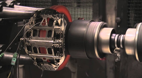


Arabalarda ve hafif ticari araçlarda fren kaliperi değişim talimatları
Lütfen tüm talimatları dikkatlice okuyun. Aynı talimatları fren kaliperi paketinden de bulabilirsiniz. Ürünün tüm ömrü boyunca bunları muhafaza etmeyi unutmayınız. Aracınızı satmanız halinde, bunları yeni sahibine teslim ediniz.
Bu montaj talimatları, standart tamir işleri için bir rehber olup, farklı fren sistemleri için geçerli olabilecek bazı farklı özellikleri göz ardı ediniz. Araç ve fren sistemi üreticileri tarafından hazırlanan özel talimatlara detaylı olarak uyulmalıdır.
Bu doküman, kaliper değişim talimatlarını içermektedir:
1. Tek-diskli fren kaliperleri
2. Çift-diskli sabit kaliperler
3. Radyal montajlı balataya sahip yüzer kaliperler, tip 2x60/68.
2. Çift-diskli sabit kaliperler
3. Radyal montajlı balataya sahip yüzer kaliperler, tip 2x60/68.
Bu talimat sayfasındaki tüm bilgiler, aksi belirtilmediği sürece her üç kaliper tipi için geçerlidir.
Değişim prosedürü
Değişim prosedürüne başlamadan önce, değişim için kullanılacak yedek parçaların, aracın marka ve modeline uygunluğundan emin olun.
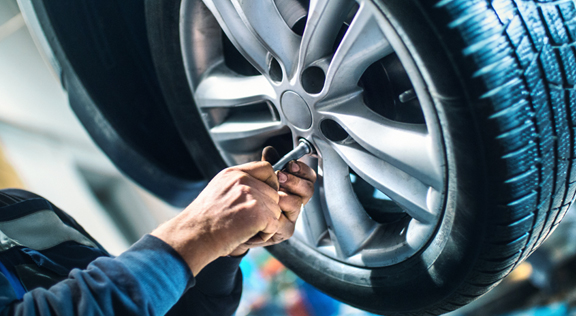
- Tekerleği sökün.
- Yeniden montajı doğru yapmak için, kısmen veya tamamen sökülen tüm bileşenlerin konumlarını not edin.

1. Varsa aşınma gösterge kablosu (madde 1) bağlantısını araçtaki terminalinden, şasi ve kaliper üzerindeki bağlantılarından çıkartmak suretiyle sökün.
2. Emniyet ayrık pimleri (madde 2) bulunan modellerde bunları pense ile sökün.

3. Eğer çift-diskli kaliper kullanılmışsa, pense ile yayları (madde 3) sökün.

4. Bir çekiç ve pim aleti kullanarak pim(ler)i (madde 4) dışarı çekin. Elinizle tamamen dışarı çekerken, yayların (madde 5) yerinde kaldığından emin olun.

5. Yay(lar)ı (madde 5) sökün. Hidrolik akışkanı seviyesini kontrol edin. Fren hidroliği haznesi kapağını açın.
DİKKAT! Aşağıda açıklanmış olan pistonu geri çekme adımları, hazne içindeki fren hidroliği seviyesinde artışa neden olacaktır. Fren hidroliği seviyesinin bir sızıntıya neden olmayacağından emin olun, aksi halde aracın boyalı kısımları zarar görebilir.
SABİT KALİPERLER tip A B
1. Bir ekartör veya uygun başka bir alet kullanarak balataların (madde 6) üzerine bastırıp, pistonları hafifçe çekin.
Piston geri çekme işlemi, sonrasında kaliperin diskten gevşetilmesine imkan verecektir.
2. Kaliper tasarımı imkan veriyorsa, balataları sökün. Aksi halde bunları, kaliperi çıkardıktan sonra sökün. Balataları tekrar kullanmayı düşünüyorsanız, üzerilerine diskin dönüş yönünü bir keçeli kalemle işaretleyin.

YÜZER KALİPERLER tip C

1. Balataları çıkartın, aynı anda kaliper gövdesini kılavuz burçlar (madde 7) üzerinde ileri geri kaydırın. Kaliper gövdesinin kaydırılması, balataları hafifçe diskten uzaklaştırarak sökülmesini kolaylaştıracaktır.

Eğer disk aşınmasının oluşturduğu girinti balataların çıkartılmasına engel oluyorsa, kaliper gövdesini sökün:
1. Bir anahtar kullanarak vidaları (madde 8) sökün

2. Bir tornavida ile kılavuz burçları yataklarından dışarı çıkartın.
3. Kılavuz burçları (madde 7), kaliper braketinden (madde 9) ayrılacak kadar dışarı çıkartın.
4. Kaliper gövdesini (madde 10) kaliper braketinden (madde 9) tamamen ayırın ve S-şekilli bir kanca kullanarak araç şasisine asın.

5. Balataları çıkartın.
6. Balataları tekrar kullanmayı düşünüyorsanız, üzerilerine diskin dönüş yönünü bir keçeli kalemle işaretleyin.
7. Arka kaliperler (park mekanizmalı) için park kontrol kablosunu (madde 11) sökün.
TEHLİKE! Fren hidroliği hatları gevşek kalmalıdır ve gerilmemelidir. Hatlar gerilirse kopabilir ve fren hidroliği dışarı akabilir.
Tüm kaliper türleri için

1. Fren hidroliği haznesi kapağını kapatın.
2. Yolcu kompartmanı içine koltuk ve fren pedalı arasına bir ayraç (madde 12) yerleştirin ve pedalın tüm işlemler boyunca basılı kaldığından emin olun.
UYARI! Bu, fren hidroliği devresinin kapalı kalmasını sağlayarak fren hidroliği sızıntısını önler.
DİKKAT! Aşağıda açıklanan tüm aşamalar esnasında, fren hidroliğinin aracın zarar görebilecek kısımlarıyla, özellikle boyalı kısımlarıyla temas etmesine izin vermeyin. Kazara olabilecek hidrolik sıçramaları veya sızıntılarını derhal bir mutfak havlusu ile silin ve suyla temizleyin.

3. Kaliper üzerindeki besleme hattı (madde 13) vidasını, elle tamamen açılabilecek kadar gevşetin, ancak herhangi bir fren hidroliği sızıntısına izin vermeyin.
4. Açık uçlu bir somun anahtarı kullanarak montaj vidalarını (madde 14) açın ve kaliperi akstan sökün.

5. DİKKAT! Çift-diskli kaliperlerde sadece aks bağlantı vidalarını sökün. Kaliper-yarılarını bileştiren vidaları (madde 15) sökmeyin.
6. Besleme hattını (madde 13) kaliperden tamamen sökün.
7. Fren hidroliği sızıntılarını derhal silin.
8. Kazara olabilecek hidrolik akışkanı sızıntısını önlemek için besleme borusunu yüksekte tutun.
9. Değiştirilecek kaliperi çıkartın.
9. Değiştirilecek kaliperi çıkartın.
Montaj prosedürü

1. Balataları (madde 16) yeni kalipere takın.
UYARI! Balataların üzerindeki ok işaretlerinin, disk dönüş yönünü göstermesi gereklidir.
TEHLİKE! Balataların, sürtünme malzemesi diske bakacak şekilde yerleştirilmesi gereklidir.

2. UYARI! Kaliper tasarımı izin veriyorsa, balatalar ayrıca kaliper takıldıktan sonra, “vidaları sıkın ve sabitleyin” adımından hemen sonra yerleştirilebilir.
TEHLİKE! Sürtünme yüzeylerinin gresle kirlenmediğinden emin olun, aksi halde tüm gres kalıntılarının zımpara ile giderilmesi gerekir.

3. Yayları (madde 5) ve pimleri (madde 4), kaliper ve balatalardaki ilgili yerlerine yeniden takın. Pimler, bir çekiç ve pim aleti kullanılarak sonuna kadar geçirilmelidir.
Yayları takarken yerleşim yönüne dikkat edin.

4. yayların doğru yerleştirildiğini kontrol edin.

5. Emniyet ayrık pimleri (madde 2) bulunan modellerde bunları pense ile geri yerleştirin.

6. Ayrık pimlerin doğru yerleştirildiğini kontrol edin.
7. Disk (madde 18) üzerindeki frenleme yüzeyini (madde 17) bir yağ çözücüyle (örn. Solvent SE 47) temizleyin.
8. Yeni kaliperi aks üzerine yerleştirin, diski (madde 18) balatalar arasına geçirin.
9. Sabitleme vidalarını (madde 14) açık uçlu bir anahtar ile sıkın, araç üreticisi tarafından verilen sıkma torku değerlerini uygulayın.
Alternatif olarak, aşağıdaki sıkma torku değerlerini referans alabilirsiniz:
| Vida türü | M12x1,25 | M12x1,5 | M14x1,5 |
| Sıkma torku | 115 Nm | 125 Nm | 180 Nm |
10. Varsa aşınma gösterge kablosunu araçtaki terminaline ve şasi ve kaliper üzerindeki bağlantılarına yeniden bağlayın.

11. Fren hidroliği besleme hattını (madde 13) geri bağlayın.
12. Daha önce yolcu kompartmanı içine yerleştirmiş olduğunuz ayracı çıkartarak fren pedalını serbest bırakın ve devrenin yeninden açılmasını sağlayın.
13. C tipi arka kaliperler (park mekanizmalı) için park kontrol kablosunu (madde 11) geri bağlayın.
14. Kol kilit pimini (madde 19) çıkartın.
15. Aracın içinden el frenini uygulayın. Frenleme mekanizması kolu hareketi yeniden minimum değerlere gelene kadar işlemi çok kez tekrar edin.
16. Fren hidroliği haznesi kapağını açın.

17. Koruyucu kapağı (madde 20) çıkartın ve kaliper üzerindeki tahliye tapasına (nokta 21) şeffaf bir hortum bağlayın; hidrolik akışkanını toplamak için hortumun diğer ucu altına bir kap yerleştirin.

18. Tahliye tapasını (madde 21) açın.
19. Aracın fren pedalına fren hidroliği tahliye tapasından akmaya başlayana kadar üst üste basın.
20. Pedalı basılı tutarak tahliye tapasını kapatın. Pedalı serbest bırakın, bir kaç saniye bekledikten sonra fren akışkanı herhangi bir hava kabarcığı olmaksızın akana ve fren pedalının normal direnci ve hareket mesafesi geri kazanılana kadar işlemi tekrar edin.
21. Tabloda verilen sıkma torklarını kullanarak, tahliye tapası vidasını sıkın:
| Tahliye tapası | M6x1 | M6x1 | M6x1 | M6x1 |
| Sıkma torku | 5÷7 Nm | 7÷10 Nm | 17÷20 Nm | 18÷22 Nm |
22. Şeffaf hortumu çıkartın ve koruyucu kapağı tahliye tapası üzerine geri takın.
23. Diğer tahliye tapaları için de tahliye işlemini tekrar edin.
24. Tahliye işlemi sonrasında kaliper içindeki pistonları uygun bir alet kullanarak (ekartör gibi) tamamen geri çekin ve sonrasında hidrolik akışkanı seviyesini üreticinin tavsiyesine göre tamamlayın.
25. Fren hidroliği haznesi kapağını kapatın.
26. Motor çalışıyor haldeyken, aracın fren pedalına güçlü bir baskı uygulayın ve kaliperden herhangi bir hidrolik sızıntısı ya da devrede anormal bir basınç kaybı olmadığını ve arka fren lambalarının yandığını kontrol edin.
TEHLİKE! Kaliperden hidrolik sızıntısı varsa, nedenini bulmak ve sorunu çözmek için bu dokümanda belirtilen tüm adımları tekrar edin.

27. Birleşik el frenli kaliperlerde el freni kablosu terminalini kaliper üzerindeki yerine bağlayın. Kabin el frenini üst üste çekip serbest bırakın.
28. Tekerleği geri takın.
29. Balatalar yeniyse, yedek balata ile verilen talimatları izleyerek alıştırma yapın.
Fren kaliperlerinin değiştirilmesine ilişkin talimatları burada bulabilirsiniz:
Merkezi yaylı yüzer kaliperler

2 veya 4 yan yaylı ve artık tork azaltıcı yaylı yüzer kaliperler.

Bu talimat sayfasındaki tüm bilgiler, aksi belirtilmediği sürece her iki kaliper tipi için geçerlidir.
Değişim prosedürü
Değişim prosedürüne başlamadan önce, değişim için kullanılacak yedek parçaların, aracın marka ve modeline uygunluğundan emin olun.
- Tekerleği sökün
- Yeniden montajı doğru yapmak için, kısmen veya tamamen sökülen tüm bileşenlerin konumlarını not edin.

1. Varsa aşınma göstergesi (madde 1) bağlantısını araçtaki terminalden kesin ve onu kalipere sabitleyen ayar sacından (madde 2) ve şasi üzerindeki diğer tüm bağlantılardan serbest bırakın.

2. Koruyucu kapakları (madde 3) kılavuz burçlardan sökün.
3. Eğer kapağın dudağı (madde 4) varsa, dudağı (madde 4) parmaklarınızla çekerek kapağı çıkartın.
4. Eğer kapak sert plastikten (madde 5) yapılmışsa, bir tornavida ile kaldırın. Kapak söküldüğünde kırılacaktır.
UYARI! Sökülen sert plastik kapakları yeniden kullanmayın.
DİKKAT! Sökülecek kılavuz burç, kaliper gövdesinin fren hidroliği besleme hattını germeden dönmesine izin verecek burç olmalıdır.
UYARI! İki tür kılavuz burç bulunmaktadır:
- ayrı vidalı
- birleşik vidalı
- birleşik vidalı

5. Bir anahtar yardımıyla vidayı (nokta 6) veya birleşik kılavuz burcu (nokta 7) gevşetin ve tamamen çıkarın
UYARI! Kalipere yapıştırılmış herhangi bir fren balatası varsa, bir tornavida ile ayırın.
TEHLİKE! Kaliper gövdesinin açılması, artık tork azaltma yaylarının fırlayarak açılmasına neden olabilir.

6. Birleşik olmayan kılavuz burçta (madde 8), kılavuz burcu bir tornavida ile yatağından kaldırarak kaliper braketinden (madde 9) çıkartın.
7. Süspansiyonlu ve yaprak yaylı arka tekerleklerde kaliperi değiştirirken, kaliper gövdesinin (madde 10) kaliper braketinden (madde 9) tamamen ayrılması için her iki kılavuz burcun (madde 8) sökülmesi gerekir.

8. Kaliper gövdesini (madde 10) kaliper braketinden (madde 9) diğer kılavuz burcu etrafından balatalar kaliper braketinden çıkana kadar çevirmek suretiyle çekerek uzaklaştırın. Kaliper gövdesini araç şasisine uygun desteklerle bağlayın.

9. Balataları (madde 11) ve yayları (madde 12) yeni kaliper üzerine yeniden monte edebilmek için zarar vermeden çıkartın.

10. Yanlış montajı önlemek için diskin dönüş yönünü balatlar üzerine bir keçeli kalemle işaretleyin.
11. Hala yerindeyse, artık tork azaltıcı yayları (madde 13) çıkartın.

12. Yolcu kompartmanı içine koltuk ve fren pedalı arasına bir ayraç (madde 14) yerleştirin ve pedalın tüm işlemler boyunca basılı kaldığından emin olun.
UYARI! Bu, fren hidroliği devresinin kapalı kalmasını sağlayarak fren hidroliği sızıntısını önler.
DİKKAT! Aşağıda açıklanan tüm aşamalar esnasında, fren hidroliğinin aracın zarar görebilecek kısımlarıyla, özellikle boyalı kısımlarıyla temas etmesine izin vermeyin. Kazara olabilecek fren hidroliği sıçramaları veya sızıntılarını derhal bir mutfak havlusu ile silin ve suyla temizleyin.

13. Kaliper üzerindeki besleme hattı (madde 15) vidasını, elle tamamen açılabilecek kadar gevşetin, böylece herhangi bir fren hidroliği sızıntısı önlenecektir.
14. Açık uçlu bir somun anahtarı kullanarak montaj cıvatalarını (madde 16) açın ve kaliper braketini (madde 9) göbek braketinden sökün.
15. Besleme hattını (madde 15) kaliper gövdesinden tamamen sökün.
16. Fren hidroliği sızıntılarını derhal silin.
17. Herhangi bir hidrolik akışkanı sızıntısını önlemek için besleme borusunu yüksekte tutun.
18. Birleşik el frenli kaliperlerde el freni kablosunu kaliper üzerindeki yerinden sökün.
19. Değiştirilecek kaliperi çıkartın.
20. Disk üzerindeki frenleme yüzeylerini (madde 17) bir yağ çözücüyle (örn. Solvent SE47) temizleyin.
Kaliper montaj prosedürü
DİKKAT! Yeni kaliper üzerindeki hidrolik giriş deliğinin koruyucu kapağını, besleme hattını bağlayana kadar sökmeyin.
Yeni kaliperi takmadan önce verilen gresi kullanarak burçları ve toz kapaklarını yağlayın.
UYARI! EUH210 - Malzeme güvenlik bilgi formu talep edilmesi halinde mevcuttur.
UYARI! EUH208 - N-alkilleştirilmiş benzotriazol içerir. Alerjik reaksiyona neden olabilir.
1. Varsa burçlar üzerindeki koruyucu kapakları çıkartın
2. Vidaları veya birleşik vidalı kılavuz burçlarını gevşetin
3. Ayrı vida durumunda vidaları tamamen çıkartın
4. Kaliper gövdesini kaliper desteğinden uzağa çekin
UYARI! Toz kapaklarının zarar görmesini önlemek için burçları kapağın yan tarafından çekip çıkartın.
5. Kapakları çıkarın.
6. Monte edilecek tüm bileşenleri, burç yataklarını iyice temizleyin ve uygun ürünler (örn. nemli bez) kullanarak yatakların üzerini kapatın.
7. Göbek braketi üzerindeki montaj yüzeylerini temizleyin.

8. Yeni kaliper braketini (madde 18) diskin içine takarak yerleştirin.
9. İki montaj vidasını (madde 19 ve 20) takın ve yaklaştırın.
10. Disk giriş tarafındaki montaj cıvatasını (madde 19) sıkın (ileri viteste) ve araç üreticisi tarafından önerilen sıkma torkunu uygulayın.
11. İkinci montaj cıvatasını (madde 20) (disk çıkış tarafı) araç üreticisi tarafından verilen sıkma torku değerlerini uygulayarak sıkın.
Alternatif olarak, önerilen sıkma torku değerlerini referans alabilirsiniz:
| Vida türü | Sıkma torku |
| M12x1,25 | 115 Nm |
| M12x1,5 | 125 Nm |
| M14x1,5 | 180 Nm |
| M16x1,5 | 210 Nm |

12. Kapakların tüm iç yüzeyini (madde 21) ve kaliper gövdesi ile temas profilini (madde 22) eşit şekilde gresleyin.
13. Kapakları (madde 21) kaliper gövdesi üzerindeki yataklarına (madde 23) takın.
DİKKAT! Parmağınızla kapağın doğru şekilde takıldığını ve kaliper gövdesine oturduğunu kontrol edin.
14. Burçların (madde 24) ve kaliper gövdesindeki yataklarının (madde 25) dış yüzeyini gresleyin, burçları kaliper gövdesine kapağın karşı tarafından takın.
15. Kapaklar (madde 21) yataklarına (madde 26) yerleşene kadar burçları (madde 24) itin.

16. Gres fazlasını temizleyin.
17. Kaliper gövdesini kaliper braketine vidayı veya birleşik burcu disk çıkış tarafından (ileri viteste) dişlere geçirip sıkın.
18. Kaliper gövdesini (nokta 27), balatalar kaliper braketine girinceye kadar kılavuz burcun etrafında döndürerek kaliper braketinden (nokta 18) dışarı doğru çekin. Kaliper gövdesini araç şasisine uygun desteklerle bağlayın.
DİKKAT! Kılavuz burç yatağını bağlantı noktası olarak kullanmayın.
Balataların montajı
1. Öngörülen yerlerde, yan yayları (madde 12) kaliper braketine güvenli şekilde bağlanmasını sağlayacak yeterli baskıyı uygulamak suretiyle takın.

2. Dört yaylı kaliperlerde daima yayları, kanatlar kaliper braketinin dış tarafına bakacak şekilde monte edin.
DİKKAT! Doğru montaj yönüne uyun.
UYARI! Eğer yapışkan taraflı balata varsa, yeni balataların takılması gerekir; yedek balata ile birlikte verilen talimatları izleyin.
DİKKAT! Aşınma göstergeli balata, sökülmeden önceki orijinal yerine geri takılmalıdır.

3. Balataları (madde 11) kaliper braketi içine (madde 18) geri takın; B tipi kaliperlerde yan yayları (madde 12) kaldırarak açmak için bir tornavida kullanın.
UYARI! Balataların üzerindeki ok işaretlerinin, disk dönüş yönünü göstermesi gereklidir.
TEHLİKE! Balataların, sürtünme malzemesi diske bakacak şekilde yerleştirilmesi gereklidir.
UYARI! Balataların üzerindeki ok işaretlerinin, disk dönüş yönünü göstermesi gereklidir.
TEHLİKE! Balataların, sürtünme malzemesi diske bakacak şekilde yerleştirilmesi gereklidir.
4. Aşınma gösterge kablosunu (madde 1) ilgili kanaldan aşağıdaki şekilde geçirin:
A tipikaliperler için - yay içine (madde 28).

Tip B kaliperler için - kaliper gövdesi içine (madde 27)


4. Kaliper gövdesini (madde 27) vidalı kılavuz burcu etrafında çevirerek kaliperi dikkatlice kapatın. Yapışkan yüzeyli balata varsa, kaliper gövdesi montajını tamamlamadan önce kaliper gövdesi ile balata arasında temas oluşmamasına dikkat edin.
DİKKAT! Burçların üzerindeki koruyucu kapakların kaliper braketine çarparak hasar görmediğinden emin olarak kaliperi dikkatlice kapatın.
DİKKAT! Burçların üzerindeki koruyucu kapakların kaliper braketine çarparak hasar görmediğinden emin olarak kaliperi dikkatlice kapatın.

5. Kaliper gövdesini (madde 27) kaliper diskine (madde 18) doğru hareket ettirin.
6. Kılavuz burcunu (madde 29) kaliper braketi yatağına geri takın.

7. Gereken yerlere yeni vida (madde 30) takın ve sıkın.

8. Süspansiyonlu ve yaprak yaylı arka tekerleklerdeki kaliperi değiştirirken, kaliper gövdesinin (madde 27) kaliper braketi (madde 18) üzerine geri yerleştirilmesi gerekir, daha sonra her iki kılavuz burcu (madde 29) geri takın ve ilgili yerlere iki yeni vidayı (madde 30) takın ve sıkın.

9. Henüz vidalanmamışsa, disk giriş tarafındaki (ileri viteste) kılavuz burç sabitleme vidasını veya birleşik kılavuz burcunu sıkın. Daha sonra diğer vidayı veya diğer birleşik kılavuz burcunu aynı torkta sıkın.
10. Aşağıdaki tabloda belirtilen sıkma torkunda sıkın:
| Tip | Sıkma torku | |
| Sabitleme vidası | (M8 – CH6) | 32 ÷ 36 Nm |
| Birleşik vidalı kılavuz burç | (M8 – CH6) | 32 ÷ 36 Nm |
| Birleşik vidalı kılavuz burç | (M10 – CH8) | 65 ÷ 75 Nm |
TEHLİKE! Açıklanan sıkma sırasını izleyin; aksi halde kaliper doğru çalışmayabilir.
11. Artık tork azaltma yaylarında (madde 31), yayı balatanın plakası (madde 32) altına asın ve plakanın alt tarafını oyuk uçlu bir tornavida yardımıyla diğer balataya asın.
TEHLİKE! Yanlış yay bağlantısı, fırlayarak açılmasına neden olabilir.
DİKKAT! Doğru montaj yönüne uyun.

12. Yerinde kalmalarını sağlamak için parçaları (madde 33) dikkatlice temizleyin ve yedek parça setinde verilen gres ile bunların iç yüzeylerini ve kaliper gövdesi yatağını gresleyerek yeni koruyucu kapakları (madde 34) takın.
13. Koruyucu kapağı (madde 34), yatağına (madde 35) tamamen oturacak şekilde çevirin.
14. Varsa aşınma göstergesini araçtaki terminale yeniden bağlayın, kaliper üzerindeki ayar sacına hafif bir baskı ile sabitleyin ve şasi üzerindeki bağlantıları da sabitleyin.
15. Fren hidroliği giriş deliği (madde 36) üzerindeki koruyucu kapağı çıkartın.
16. Fren hidroliği besleme hattını geri bağlayın.
17. Daha önce yolcu kompartmanı içine yerleştirmiş olduğunuz ayracı çıkartarak fren pedalını serbest bırakın ve hidrolik devrenin yeninden açılmasını sağlayın.
18. Fren hidroliği haznesi kapağını açın.

19. Koruyucu kapağı (madde 37) çıkartın ve kaliper üzerindeki tahliye tapasına (nokta 38) şeffaf bir hortum bağlayın; hidrolik akışkanını toplamak için hortumun diğer ucu altına bir kap yerleştirin.

20. Tahliye tapasını (madde 38) açın.
21. Aracın fren pedalına fren hidroliği tahliye tapasından akmaya başlayana kadar üst üste basın.
22. Pedalı basılı tutarak tahliye tapasını kapatın. Pedalı serbest bırakın, bir kaç saniye bekledikten sonra fren akışkanı herhangi bir hava kabarcığı olmaksızın akana ve fren pedalının normal direnci ve hareket mesafesi geri kazanılana kadar işlemi tekrar edin.
23. Tabloda verilen sıkma torklarını kullanarak, tahliye tapası vidasını sıkın:
| Tahliye tapası | M6x1 | M8x1,25 | M10x1 | M12x1 |
| Sıkma torku | 5÷7 Nm | 7÷10 Nm | 17÷20 Nm | 18÷22 Nm |
24. Şeffaf hortumu çıkartın ve koruyucu kapağı tahliye tapası üzerine geri takın.
25. Diğer tahliye tapaları için de tahliye işlemini tekrar edin.
26. Tahliye işlemi sonrasında kaliper içindeki pistonları uygun bir alet kullanarak (ekartör gibi) tamamen geri çekin ve sonrasında hidrolik akışkanı seviyesini üreticinin tavsiyesine göre tamamlayın.
27. Fren hidroliği haznesi kapağını kapatın.
28. Motor çalışıyor haldeyken, aracın fren pedalına güçlü bir baskı uygulayın ve kaliperden herhangi bir hidrolik sızıntısı ya da devrede anormal bir basınç kaybı olmadığını ve arka fren lambalarının yandığını kontrol edin.
TEHLİKE! Kaliperden hidrolik sızıntısı varsa, nedenini bulmak ve sorunu çözmek için bu dokümanda belirtilen tüm adımları tekrar edin.
29. Birleşik el frenli kaliperlerde el freni kablosu terminalini kaliper üzerindeki yerine bağlayın.

30. Kabin el frenini üst üste çekip serbest bırakın.
31. Tekerleği geri takın.
32. Balatalar yeniyse, yedek balata ile verilen talimatları izleyerek alıştırma yapın.
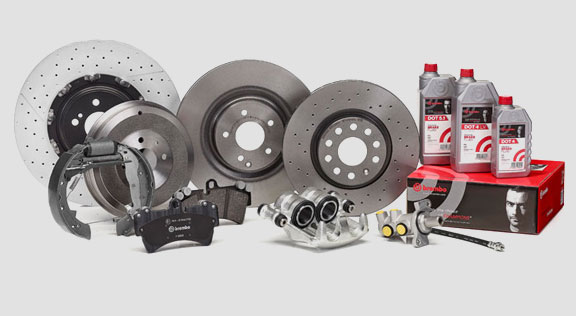
Burada, elektrikli park mekanizmalı ticari araçlar için yüzer kaliperler (ECS53 ve ECS60 tipi) bileşenlerinin değiştirilmesine yönelik talimatlar yer almaktadır:
1. Aktüatör ünitesi
2. Balatalar
3. Kaliper gövdesi (balatasız ve kaliper braketsiz)
4. Kaliper braketi
2. Balatalar
3. Kaliper gövdesi (balatasız ve kaliper braketsiz)
4. Kaliper braketi
UYARI! Pakette yer alan yedek parçaları değiştirmeden önce bu dokümanı okuyun. Sadece pakette yer alan yedek parçayı veya parçaları değiştirmek için gereken adımları gerçekleştirin.
Değişim prosedürü
Değişim prosedürüne başlamadan önce, değişim için kullanılacak yedek parçaların, aracın marka ve modeline uygunluğundan emin olun.
UYARI! Bir elektrik arızası durumunda, aktüatör ünitesini sökün ve uygun bir anahtar ile torks vidasını saat yönünde çevirerek pistonu geri çekin.
- Yeniden montajı doğru yapmak için, kısmen veya tamamen sökülen tüm bileşenlerin konumlarını not edin.

1. Arıza tespit aracını (Tümleşik Arıza Tespit - OBD) araca bağlayın ve araç üreticisi tarafından açıklanan şekilde bakım modu prosedürüne alın.
DİKKAT! Yedek parçanın araç yazılımıyla uyumlu olduğundan emin olun.
2. Tekerleği sökün.

3. Aktüatör ünitesi elektrik besleme kablosunu kablo rakorundan çıkartın.
4. ECS60 kaliper tipi için kablo rakorunu (madde 5) gevşetin ve çıkartın.
5. Elektrik besleme kablosunu (madde 6) aktüatör ünitesinden sökün.
UYARI! Konnektör, bir emniyet mandalı ile takılmış olabilir.
UYARI! Konnektör, bir emniyet mandalı ile takılmış olabilir.
Aktüatör ünitesinin sökülmesi
UYARI! Sadece ayrı bir yedek parça mevcut ise aktüatör ünitesinin sökülmesine devam edin.
1. Aktüatör ünitesinin (madde 1) sabitleme vidalarını (madde 7) gevşetin
2. Aktüatör ünitesini (madde 1) sökün
3. Sızdırmazlığı (madde 8) sökün.

Balataların sökülmesi
DİKKAT! Yeniden kullanmayı planladığınız herhangi bir bileşene zarar vermeyin.
TEHLİKE! Fren hidroliği besleme hattının gerilmesine neden olmayın.

1. Varsa aşınma göstergesi (madde 9) bağlantısını araçtaki terminalden kesin ve onu kalipere sabitleyen ayar sacından ve şasi üzerindeki diğer tüm bağlantılardan serbest bırakın.
2. Koruyucu kapağı (madde 10) ikincil burçtan (ileri tahrik dönüş diski çıkış tarafı) çıkartın.

3. Eğer kapak sert plastikten (madde 11) yapılmışsa, bir tornavida ile kaldırın. Kapak söküldüğünde kırılacaktır.
UYARI! Sökülen sert plastik kapakları yeniden kullanmayın.
4. İkincil vidayı (madde 12) gevşetin ve çıkartın.
5. ECS60 tipi kaliperde bir tornavida kullanarak burcu yivinden kaldırın ve kaliper braketinden serbest bırakın.

6. Koruyucu kapağı (madde 14) birincil burçtan (ileri tahrik dönüş diski giriş tarafı) çıkartın.
7. Birincil vidayı (madde 15) tamamen gevşetin ve sökün.
UYARI! Bir tornavida ile kılavuz burçları yivlerinden kaldırıp çıkartın.
8. Birincil kılavuz burcu (madde 16), kaliper braketinden ayrılacak kadar dışarı çıkartın.

9. Kaliper gövdesini (madde 3) kaliper braketinden (madde 4) çekin, fren hidroliği besleme hattının gerilmemesine dikkat edin.
10. Kaliper gövdesini araç şasisine uygun desteklerle bağlayın.
DİKKAT! Burç yatağını bağlantı noktası olarak kullanmayın.

11. Balataları (madde 17) ve yayları (madde 18) yeni kaliper üzerine yeniden monte edebilmek için zarar vermeden çıkartın.

12. Hala yerindeyse, artık tork azaltıcı yayları (madde 19) çıkartın.
UYARI! Aynı balataların doğru şekilde geri takılması için, diskin dönüş yönünü göstermek üzere keçeli bir kalemle balatalar üzerine ok işareti (halihazırda yoksa) çizin.
Kaliper gövdesinin sökülmesi

1. Yolcu kompartmanı içine koltuk ve fren pedalı arasına bir ayraç (madde 20) yerleştirin ve pedalın tüm işlemler boyunca basılı kaldığından emin olun.
UYARI! Bu, fren hidroliği devresinin kapalı kalmasını sağlayarak fren hidroliği sızıntısını önler.
DİKKAT! Aşağıda açıklanan tüm aşamalar esnasında, fren hidroliğinin aracın zarar görebilecek kısımlarıyla, özellikle boyalı kısımlarıyla temas etmesine izin vermeyin. Kazara olabilecek fren hidroliği sıçramaları veya sızıntılarını derhal bir mutfak havlusu ile silin ve suyla temizleyin.

2. Kaliper üzerindeki besleme hattı (madde 21) vidasını, elle tamamen açılabilecek kadar gevşetin, böylece herhangi bir fren hidroliği sızıntısı önlenecektir.
3. Besleme hattını (madde 21) kaliper gövdesinden tamamen sökün.

4. Fren hidroliği sızıntılarını derhal silin.
5. Herhangi bir hidrolik akışkanı sızıntısını önlemek için besleme borusunu yüksekte tutun.
6. Kaliper gövdesini (madde 3) ayırın.
Kaliper braketinin sökülmesi

DİKKAT! Sökme işlemi esnasında kazara düşmesini önlemek için kaliper braketini yerinde bırakın.
1. Sabitleme vidalarını (madde 22) gevşetin.
2. Kaliper braketini (madde 4) göbek braketinden sökün.
Montaj prosedürü

Yeni yedek bileşeni yeniden monte edin.
1. Monte edilecek tüm bileşenleri (gerek yeni olanlar, gerekse sökülmüş olanlar), burç yataklarını ve yay yataklarını iyice temizleyin ve uygun ürünler (örn. nemli bez) kullanarak temizleyin.
TEHLİKE! Bileşenlerin sağlam olduğundan emin olun, hasarlı olanları yenileriyle değiştirin.
2. Göbek braketi üzerindeki montaj yüzeylerini (madde 23) temizleyin.
3. Disk üzerindeki frenleme yüzeylerini (madde 24) bir yağ çözücüyle (örn. Solvent SE47) temizleyin.
Kaliper braketinin takılması

1. Yeni kaliper braketini (madde 25) göbek braketi üzerine yerleştirin.
2. Sabitleme vidalarını (madde 26) takın ve araç üreticisi tarafından verilen sıkma torku değerlerine sıkın.
Kaliper gövdesinin takılması

1. Yayları (madde 27), yataklarının içine yerleştirerek geri takın.

2. Dört yaylı tip ECS52 kaliperi daima kanatlar (madde 28) kaliper braketinin dış tarafına bakacak şekilde monte edin.
UYARI! Eğer yapışkan taraflı balata varsa, yeni balataların takılması gerekir; yedek balata ile birlikte verilen talimatları izleyin.
DİKKAT! Aşınma göstergeli balata, sökülmeden önceki orijinal yerine geri takılmalıdır.
TEHLİKE! Balataların, sürtünme malzemesi diske bakacak şekilde yerleştirilmesi gereklidir.

3. Balataları (madde 29) kaliper braketi içine (madde 25) geri takın; yan yayları (madde 27) kaldırarak açmak için bir tornavida kullanın.

4. Artık tork azaltma yaylarında (madde 30), yayı balatanın plakası (madde 31) altına asın ve plakanın alt tarafını oyuk uçlu bir tornavida yardımıyla diğer balataya asın.
TEHLİKE! Yanlış yay bağlantısı, fırlayarak açılmasına neden olabilir.
TEHLİKE! Yanlış yay bağlantısı, fırlayarak açılmasına neden olabilir.

DİKKAT! Doğru montaj yönüne uyun.
DİKKAT! Eğer kaliper gövdesi yeniyse, yeni kaliper üzerindeki hidrolik giriş deliğinin koruyucu kapağını, besleme hattını bağlayana kadar sökmeyin.
6. Kaliper gövdesini (madde 32), burçlar kaliper braketi üzerindeki deliklere denk gelecek şekilde diskin içine takarak yerleştirin.
DİKKAT! Kapaklara zarar vermeyin.
7. Kılavuz burçları (madde 33) kaliper braketi üzerindeki yataklarına itin.
8. Vidaları (madde 34) takın ve 32 ÷ 36 Nm torkuna sıkın.
9. Kapakları (madde 35) yerleştirin.
DİKKAT! Koruyucu kapağı çıkartmadan önce, besleme noktasını mümkün olduğunca yüksekte tutarak kaliper içindeki fren hidroliğinin sızmadığına emin olun.
10. Varsa aşınma göstergesi kablosunu araçtaki terminale yeniden bağlayın, kaliper üzerindeki ayar sacına hafif bir baskı ile sabitleyin ve varsa şasi üzerindeki bağlantıları da sabitleyin.

Fren hidroliği besleme hattının bağlanması

1. Koruyucu kapağı (madde 36) fren hidroliği giriş deliğinden çıkartın.
2. Fren hidroliği besleme hattını (madde 21) geri bağlayın.
3. Daha önce yolcu kompartmanı içine yerleştirmiş olduğunuz ayracı çıkartarak fren pedalını serbest bırakın ve devrenin yeninden açılmasını sağlayın.

4. Koruyucu kapağı (madde 37) tahliye tapasından (madde 38) çıkartın.
5. Kaliper üzerindeki tahliye tapasına (nokta 38) şeffaf bir hortum bağlayın, hidrolik akışkanını toplamak için hortumun diğer ucu altına bir kap yerleştirin.

6. Tahliye tapasını (madde 38) açın.
7. Aracın fren pedalına fren hidroliği tahliye tapasından akmaya başlayana kadar üst üste basın.
8. Pedalı basılı tutarak tahliye tapasını kapatın. Pedalı serbest bırakın, bir kaç saniye bekledikten sonra fren akışkanı herhangi bir hava kabarcığı olmaksızın akana ve fren pedalının normal direnci ve hareket mesafesi geri kazanılana kadar işlemi tekrar edin.
9. Aşağıdaki tabloda verilen sıkma torklarını uygulayarak, tahliye tapasını (madde 38) sıkın:
| Tahliye tipi | M10x1 |
| Sıkma torku | 12÷16 Nm |
10. Şeffaf boruyu çıkartın.
11. Diğer tahliye tapaları için de tahliye işlemini tekrar edin.
12. Koruyucu kapağı (madde 37) tekrar yerleştirin.
13. Tahliye işlemi sonrasında kaliper içindeki pistonları uygun bir alet kullanarak (ekartör gibi) tamamen geri çekin ve sonrasında hidrolik akışkanı seviyesini üreticinin tavsiyesine göre tamamlayın.
14. Motor çalışıyor haldeyken, aracın fren pedalına güçlü bir baskı uygulayın ve kaliperden herhangi bir hidrolik sızıntısı ya da devrede anormal bir basınç kaybı olmadığını ve arka fren lambalarının yandığını kontrol edin.
TEHLİKE! Kaliperden hidrolik sızıntısı varsa, nedenini bulmak ve sorunu çözmek için bu dokümanda belirtilen tüm adımları tekrar edin.

Aktüatör ünitesinin montajı
UYARI! Aktüatör ünitesi, halihazırda kaliper gövdesine montajlı temin edilmiş olabilir.
Yeni yedek bileşeni yeniden monte edin.
- Yeniden monte etmeden önce daha önceden söktüğünüz tüm bileşenleri temizleyin.
DİKKAT! Diş tutucu ile her zaman yeni vidalar kullanın. Daima yen bir sızdırmazlık takın.
TEHLİKE! Bileşenlerin sağlam olduğundan emin olun, hasarlı olanları yenileriyle değiştirin

1. Kaliper ve aktüatör ünitesindeki temas yüzeyini temizleyin.
2. Dişli vida yataklarındaki diş tutucu kalıntılarını giderin.
3. Sızdırmazlığı (madde 39) temizleyin ve verilen gresle yağlayın.
4. Aktüatör ünitesi kuplajının iç çapını verilen gresle yağlayın.
UYARI! EUH210 - Malzeme güvenlik bilgi formu talep edilmesi halinde mevcuttur.
UYARI! EUH208 - N-alkilleştirilmiş benzotriazol içerir. Alerjik reaksiyona neden olabilir.

5. Sızdırmazlıkları (madde 39) kaliper gövdesi üzerindeki yataklarına (madde 40) yerleştirin.
6. Aktüatör ünitesini (madde 41) kaliper gövdesi üzerindeki torks vidasına (madde 42) takın.
7. Aktüatör ünitesini (madde 41), sabitleme vidalarının (madde 44) delikleri (madde 43) orijinal montaj konumuna denk gelecek şekilde çevirin.
DİKKAT! Aktüatör ünitesini kaliper gövdesine takarken sızdırmazlık elemanını sıkıştırmayın (madde 39).
8. Sabitleme vidalarını (madde 44) takın ve 7 ÷ 10 Nm torkuna sıkın.

9. Varsa koruyucu kapağı (madde 45) çıkartın ve elektrik besleme kablosunu (madde 6) bağlayın.
10. Daha önceden söküldüyse, kablo rakorunu (madde 5) vidalayın.
11. Aktüatör ünitesi elektrik besleme kablosunu (madde 6) kablo rakoruna (madde 5) sabitleyin.
Son aşamalar
1. Tekerleği geri takın.
2. Sıfırlama prosedürünü (Montaj kontrolü) gerçekleştirin.
3. Gerekiyorsa, sayaçları araç üreticisi tarafından açıklanan şekilde sıfırlayın (Dahili Sayaçları Sıfırlama).
4. Araç üreticisi tarafından istenmişse, balataları alıştırın.
5. Arıza tespit aygıtı bağlantısını kesin. (Tümleşik Arıza Tespiti - OBD).
2'li veya 4'lü yan yaylara ve artık tork azaltıcı yaylara sahip yüzer kaliperler için kaliper gövdesinin değiştirilmesine yönelik talimatları burada bulabilirsiniz.
Sadece sabitleme vidalarını değiştiriyorsanız, sadece ilgili bölümlere bakın.

Değişim prosedürü
Değişim prosedürüne başlamadan önce, değişim için kullanılacak yedek parçaların, aracın marka ve modeline uygunluğundan emin olun.
- Yeniden montajı doğru yapmak için, kısmen veya tamamen sökülen tüm bileşenlerin konumlarını not edin.
- Tekerleği sökün.
ECS kaliperleri için
UYARI! Bir elektrik arızası durumunda, aktüatör ünitesini (madde 5) sökün ve uygun bir anahtar ile torks vidasını saat yönünde çevirerek pistonu geri çekin.

1. Arıza tespit aracını (Tümleşik Arıza Tespit - OBD) araca bağlayın ve araç üreticisi tarafından açıklanan şekilde bakım modu prosedürüne alın.
DİKKAT! Bu işlem olmadan piston, ekartör veya başka uygun bir aletle geri çekilemez.
DİKKAT! Yedek parçanın araç yazılımıyla uyumlu olduğundan emin olun.

2. Elektrik besleme kablosunu (madde 2) aktüatör ünitesinden sökün.
UYARI! Konnektör, bir emniyet mandalı ile takılmış olabilir.
Tüm kaliper türleri için

1. El frenli kaliperlerde, kontrol kablosunu (madde 3) kaliperden çıkartın.

2. Varsa, aşınma gösterge (nokta 4) bağlantısını araçtaki terminalden ayırın, kalipere sabitleyen şimden (nokta 5) ve şasi üzerindeki herhangi bir bağlantıdan kurtarın.

3. Koruyucu kapakları (madde 6) kılavuz burçlardan sökün.
4. Eğer kapağın dudağı (madde 7) varsa, dudağı (madde 7) parmaklarınızla çekerek kapağı çıkartın.

5. Eğer kapak sert plastikten (madde 8) yapılmışsa, bir tornavida ile kaldırın. Kapak söküldüğünde kırılacaktır.
UYARI! Sökülen sert plastik kapakları yeniden kullanmayın.
DİKKAT! Sökülecek kılavuz burç, kaliper gövdesinin fren hidroliği besleme hattını germeden dönmesine izin verecek burç olmalıdır.
UYARI! İki tip kılavuz burç vardır: ayrı vidalı, birleşik vidalı.
UYARI! Sökülen sert plastik kapakları yeniden kullanmayın.
DİKKAT! Sökülecek kılavuz burç, kaliper gövdesinin fren hidroliği besleme hattını germeden dönmesine izin verecek burç olmalıdır.
UYARI! İki tip kılavuz burç vardır: ayrı vidalı, birleşik vidalı.

6. Vidayı (madde 9) veya birleşik kılavuz burcunu (madde 10) bir anahtarla gevşetin ve tamamen sökün.

7. Birleşik olmayan kılavuz burçta (madde 11), kılavuz burcu bir tornavida ile yatağından kaldırarak kaliper braketinden (madde 12) çıkartın.

8. Süspansiyonlu ve yaprak yaylı arka tekerleklerde kaliperi değiştirirken, kaliper gövdesinin (madde 13) kaliper braketinden (madde 12) tamamen ayrılması için her iki kılavuz burcun (madde 11) sökülmesi gerekir.
UYARI! IKalipere yapışık fren balataları varsa, kaliperin kauçuk kısımlarına zarar vermemeye özen göstererek buları bir tornavida ile ayırın.
TEHLİKE! Kaliper gövdesinin açılması, artık tork azaltma yaylarının fırlayarak açılmasına neden olabilir.

9. Kaliper gövdesini (madde 13) kaliper braketinden (madde 12) diğer kılavuz burcu etrafından balatalar (madde 14) kaliper braketinden çıkana kadar çevirmek suretiyle çekerek uzaklaştırın. Kaliper gövdesini araç şasisine uygun desteklerle bağlayın. Burç yatağını bağlantı noktası olarak kullanmayın.

11. Balataları (madde 14) zarar vermeden çıkartın.
12. Yanlış montajı önlemek için diskin dönüş yönünü balatlar üzerine bir keçeli kalemle işaretleyin.

14. Hala yerindeyse, artık tork azaltıcı yayları (madde 15) çıkartın.

15. Yolcu kompartmanı içine koltuk ve fren pedalı arasına bir ayraç (madde 16) yerleştirin ve pedalın tüm işlemler boyunca basılı kaldığından emin olun.
UYARI! Bu, fren hidroliği devresinin kapalı kalmasını sağlayarak fren hidroliği sızıntısını önler.
DİKKAT! Aşağıda açıklanan tüm aşamalar esnasında, fren hidroliğinin aracın zarar görebilecek kısımlarıyla, özellikle boyalı kısımlarıyla temas etmesine izin vermeyin. Kazara olabilecek fren hidroliği sıçramaları veya sızıntılarını derhal bir mutfak havlusu ile silin ve suyla temizleyin.
DİKKAT! Aşağıda açıklanan tüm aşamalar esnasında, fren hidroliğinin aracın zarar görebilecek kısımlarıyla, özellikle boyalı kısımlarıyla temas etmesine izin vermeyin. Kazara olabilecek fren hidroliği sıçramaları veya sızıntılarını derhal bir mutfak havlusu ile silin ve suyla temizleyin.

16. Kaliper üzerindeki besleme hattı (madde 17) vidasını, elle tamamen açılabilecek kadar gevşetin, böylece herhangi bir fren hidroliği sızıntısı önlenecektir.
17. Vidayı (madde 9) veya birleşik kılavuz burcunu (madde 10) gevşetin ve tamamen sökün.
18. Birleşik olmayan kılavuz burçta (madde 11), kılavuz burcu bir tornavida ile yatağından kaldırarak kaliper braketinden (madde 12) çıkartın.
19. Kaliper gövdesini (madde 13) kaliper braketinden (madde 12) çekin, fren hidroliği besleme hattının gerilmemesine dikkat edin.
20. Besleme hattını (madde 17) kaliper gövdesinden tamamen sökün.

21. Fren hidroliği sızıntılarını derhal silin.
22. Herhangi bir fren hidroliği sızıntısını önlemek için besleme borusunu yüksekte tutun.
23. Değiştirilecek kaliperi çıkartın.
24. Birleşik el frenli kaliperlerde el freni kablosunu kaliper üzerindeki yerinden sökün.
25. Disk üzerindeki frenleme yüzeylerini bir yağ çözücüyle (örn. Solvent SE47) temizleyin.
Balataların montajı
DİKKAT! Eğer yapışkan taraflı balata varsa, yeni balataların takılması gerekir; yedek balata ile birlikte verilen talimatları izleyin.

1.Yayların doğru yerleştirildiğini kontrol edin. Dört yaylı kaliperlerde, kanatlar her zaman kaliper braketinin dış tarafına bakacak şekilde monte edin.
DİKKAT! Yanlış yay konumu, yaralanmalara neden olabilir.

2. Balataları (madde 14) kaliper braketine (madde 12) yerleştirin. Yan yayları bastırmak için bir tornavida kullanın.
UYARI! Balataların üzerindeki ok işaretlerinin, disk dönüş yönünü göstermesi gereklidir.
TEHLİKE! Balataların, sürtünme malzemesi diske bakacak şekilde yerleştirilmesi gereklidir.
DİKKAT! Aşınma göstergeli balata, sökülmeden önceki orijinal yerine geri takılmalıdır.
UYARI! Balataların üzerindeki ok işaretlerinin, disk dönüş yönünü göstermesi gereklidir.
TEHLİKE! Balataların, sürtünme malzemesi diske bakacak şekilde yerleştirilmesi gereklidir.
DİKKAT! Aşınma göstergeli balata, sökülmeden önceki orijinal yerine geri takılmalıdır.

3. Mevcut olan yerlerde, aşınma göstergesi terminalini (madde 20) pistonu karşısındaki balataya monte edin, gerekiyorsa değiştirin.
DİKKAT! Aşınma göstergesi terminalini bağlarken, en çıkıntılı tarafın balata üzerindeki sürtünme yüzeyine baktığından emin olun.
DİKKAT! Aşınma göstergesi terminalini bağlarken, en çıkıntılı tarafın balata üzerindeki sürtünme yüzeyine baktığından emin olun.
Kaliper gövdesinin takılması
DİKKAT! El frenli kaliperler için - kaliper gövdesi fren diskinden sökülürken ve/veya fren balataları olmadığında, pistonu hidrolik olarak veya manivela kullanarak hareket ettirmeyin, yay zarar görebilir ve/veya fren hidroliği sızıntısına neden olabilir.
1. Kaliper braketi üzerinde, kaliper gövdesi ile bağlantı alanlarını (madde 21) (kılavuz yataklar) nemli bir bezle silin.
DİKKAT! Nitro-tetrakloroetilen tiner, petrol, vb. gibi koruyucu kapağa zarar verebilecek ürünler kullanmayın.
2. Kapakların tüm iç yüzeyini, kılavuz burçların dış yüzeylerini ve kaliper gövdesi içindeki yataklarını temizleyin ve eşit şekilde gresleyin.

3. İki kılavuz burçtan (madde 10) birini kaliper braketi (madde 12) üzerindeki yatağa takarak yeni kaliper gövdesini (madde 22) yerleştirin.
DİKKAT! Boruyu nihai olarak bağlayana kadar fren hidroliği giriş deliğindeki koruyucu kapağı çıkartmayın.
DİKKAT! Boruyu nihai olarak bağlayana kadar fren hidroliği giriş deliğindeki koruyucu kapağı çıkartmayın.
4. Birleşik olmayan kılavuz burçlarda (madde 11), yeni bir vida (madde 23) takın ve sıkın.
5. Kaliper gövdesini (madde 22) oturtulan kılavuz burcu etrafında çevirerek kaliperi dikkatlice kapatın.

DİKKAT! Burçların üzerindeki koruyucu kapakların kaliper desteğine çarparak hasar görmediğinden emin olarak kaliperi dikkatlice kapatın. Gerekiyorsa kapakları değiştirin.
UYARI! Yapışkan yüzeyli balata varsa, kaliper gövdesi montajını tamamlamadan önce gövde ile balata arasında temas oluşmamasına dikkat edin.
6. Aşınma göstergesi probunu (madde 20) kaliper gövdesindeki (madde 22) ilgili delikten geçirin.

7. Kılavuz burcunu (madde 10) kaliper braketi yatağına (madde 12) geri takın.
8. Birleşik olmayan kılavuz burçlarda (madde 11), yeni bir vida (madde 24) takın ve sıkın.
DİKKAT! Süspansiyonlu ve yaprak yaylı arka tekerleklerdeki kaliper braketini değiştirirken, kaliper gövdesinin kaliper braketi üzerine geri yerleştirilmesi gerekir, daha sonra her iki kılavuz burcu geri takın ve iki yeni vidayı takın ve sıkın.

9. Disk giriş tarafındaki (ileri viteste) kılavuz burç sabitleme vidasını veya birleşik kılavuz burcunu (madde 24) sıkın. Daha sonra diğer vidayı veya birleşik kılavuz burcunu (madde 25) aynı torkta sıkın.
10. Aşağıdaki tabloda belirtilen sıkma torkunda sıkın:
| Tip | Sıkma torku | |
| Sabitleme vidası | (M8 – CH6) | 32 ÷ 36 Nm |
| Birleşik vidalı kılavuz burç | (M8 – CH6) | 32 ÷ 36 Nm |
| Birleşik vidalı kılavuz burç | (M10 – CH8) | 65 ÷ 75 Nm |
TEHLİKE! Açıklanan sıkma sırasını izleyin; aksi halde kaliper doğru çalışmayabilir.

11. Artık tork azaltma yaylarında (madde 26), yayı balatanın plakası (madde 27) altına asın ve plakanın alt tarafını oyuk uçlu bir tornavida yardımıyla diğer balataya asın.
TEHLİKE! Yanlış yay bağlantısı, fırlayarak açılmasına neden olabilir.
DİKKAT! Doğru montaj yönüne uyun.

12. Yerinde kalmalarını sağlamak için parçayı (madde 28) dikkatlice temizleyin ve yedek parça setinde verilen gres ile bunların iç yüzeylerini ve kaliper gövdesi yatağını gresleyerek yeni koruyucu kapakları (madde 29) takın.
UYARI! EUH210 - Malzeme güvenlik bilgi formu talep edilmesi halinde mevcuttur.
UYARI! EUH208 - N-alkilleştirilmiş benzotriazol içerir. Alerjik reaksiyona neden olabilir.
UYARI! EUH208 - N-alkilleştirilmiş benzotriazol içerir. Alerjik reaksiyona neden olabilir.
13. Koruyucu kapakları (madde 29), yatağına (madde 30) tamamen oturacak şekilde çevirin.
14. Varsa aşınma göstergesini araçtaki terminale yeniden bağlayın, kaliper üzerindeki ayar sacına hafif bir baskı ile sabitleyin ve şasi üzerindeki bağlantıları da sabitleyin.
15. Koruyucu kapağı fren hidroliği giriş deliğinden çıkartın.
16. Fren hidroliği besleme hattını geri bağlayın.
17. Daha önce yolcu kompartmanı içine yerleştirmiş olduğunuz ayracı çıkartarak fren pedalını serbest bırakın ve devrenin yeninden açılmasını sağlayın.
El frenli kaliperler için
DİKKAT! Pistonu balatalarla birleştirmeden önce, kaliper braketinin, balataların ve diskin mevcut olduğundan emin olun.
- Pistonu balatalarla birleştirmek için manivelayı kullanın.
DİKKAT! Hidrolik çalıştırmaya sadece pistonun balatalardan mesafesi 1 mm altında olduğunda izin verilir.
Tüm kaliper türleri için
1. Kaliper üzerindeki tahliye tapasına (nokta 31) şeffaf bir hortum bağlayın, hidrolik akışkanını toplamak için hortumun diğer ucu altına bir kap yerleştirin.
2. Tahliye tapasını (madde 31) açın.
3. Aracın fren pedalına fren hidroliği tahliye tapasından akmaya başlayana kadar üst üste basın.
4. Pedalı basılı tutarak tahliye tapasını kapatın. Pedalı serbest bırakın, bir kaç saniye bekledikten sonra fren akışkanı herhangi bir hava kabarcığı olmaksızın akana ve fren pedalının normal direnci ve hareket mesafesi geri kazanılana kadar işlemi tekrar edin.
5. Tabloda verilen sıkma torklarını uygulayarak, tahliye tapasını (madde 31) sıkın:
| Tahliye tapası | M6x1 | M8x1,25 | M10x1 | M12x1 |
| Sıkma torku | 5÷7 Nm | 7÷10 Nm | 17÷20 Nm | 18÷22 Nm |

6. Şeffaf boruyu çıkartın.
7. Diğer tahliye tapaları için de tahliye işlemini tekrar edin.
8. Tahliye işlemi sonrasında kaliper içindeki pistonları uygun bir alet kullanarak (ekartör gibi) tamamen geri çekin ve sonrasında hidrolik akışkanı seviyesini üreticinin tavsiyesine göre tamamlayın.
9. Fren hidroliği haznesi kapağını kapatın.
10. Motor çalışıyor haldeyken, aracın fren pedalına güçlü bir baskı uygulayın ve kaliperden herhangi bir hidrolik sızıntısı ya da devrede anormal bir basınç kaybı olmadığını ve arka fren lambalarının yandığını kontrol edin.
TEHLİKE! Kaliperden hidrolik sızıntısı varsa, nedenini bulmak ve sorunu çözmek için bu dokümanda belirtilen tüm adımları tekrar edin.
El frenli kaliperler için
- Varsa aşınma göstergesini araçtaki terminale yeniden bağlayın, kaliper üzerindeki ayar sacına hafif bir baskı ile sabitleyin ve şasi üzerindeki bağlantıları da sabitleyin.
- Kontrol kablosunu doğru gerginliğe geri getirin.
- Araç kabinindeki el freni kolunu, normal hareket mesafesi geri kazanılana kadar üst üste çalıştırın.
ECS kaliperleri için

1. Koruyucu kapağı (varsa) çıkartın ve elektrik besleme kablosunu (madde 2) bağlayın.
2. Sıfırlama prosedürünü (Montaj kontrolü) gerçekleştirin.
3. Gerekiyorsa, sayaçları araç üreticisi tarafından açıklanan şekilde sıfırlayın (Dahili Sayaçları Sıfırlama).

4. Araç üreticisi tarafından istenmişse, balataları alıştırın.
5. Arıza tespit aygıtı bağlantısını çıkartın (Tümleşik Arıza Tespiti - OBD).
Tüm kaliper türleri için
1. Tekerleği geri takın.
2. Balatalar yeniyse, yedek balata ile verilen talimatları izleyerek alıştırma yapın.
2. Balatalar yeniyse, yedek balata ile verilen talimatları izleyerek alıştırma yapın.
Garanti sınırlamaları
Bu garanti, ürünün teslimatından sonraki iki yıl içindeki tüm uygunsuzluk ayıplarını kapsar. Tüketicinin uygunsuzluk ayıplarını, ayıbın giderilmesi için işlem yapma süresine yönelik garanti süresi limitinin, ürünün tesliminden sonraki yirmi altı ay olduğu gerçeğini değiştirmeksizin, söz konusu ayıbın tespitinden itibaren iki ay içinde bildirmesi gereklidir. Bir uygunsuzluk ayıbı olması halinde kullanıcının, yerine göre Tüketici Kanunun 130. maddesine uygun olarak ürünü tamir ettirme veya değiştirme ya da uygun bir fiyat indirimi veya kontrat feshini talep etme hakkı vardır.
Bu garanti, bu ürünle ilgili olarak verilen tek garanti olup, sözlü veya yazılı olarak verilen tüm garantilerin yerine geçer.
Bir ayıp tespit edilmesi durumunda, kullanıcının şunları yapması gereklidir:
- iptal cezası kapsamında üreticiyi ve distribütörü altı gün içinde yazılı olarak bilgilendirmek; aynı zamanda kullanıcının iade edilen Ürün veya parçaları üzerinde tespit edilen ayıbın bir açıklamasını ve Ürünün tanımı ile satın alma tarihini (perakende olarak mı satıldığını veya Ürün tertibatı parçası olarak distribütör tarafından mı satıldığını) gösteren orijinal kullanıcı satın alma belgesini sunmalıdır;
- ayıplı olduğu iddia edilen Ürünü, 25 -24035 Curno (BG) - İtalya'da bulunan Brembo S.p.A. genel merkezine dağıtım zinciri aracılığıyla göndermelidir.
Garanti, aşağıdakiler için geçerli değildir:
- Ürüne kısmen veya tamamen yanlış kullanım, kaza, yangın, kimyasal aşınma, belirtilenin haricindeki amaçlar için kullanım, kötüye kullanım, belirtilenin haricindeki modellerde kullanım, Üretici talimatlarına aykırı montaj, veya verilen talimatlarda Üretici tarafından belirtilen şekilde Ürün bakımının yapılmamasına bağlı hasarlar;
- konfor, gürültü, titreşim veya sert sürüş özellikleri ile alakalı şikayetler.
Ürün, Brembo kataloglarında ve/veya Brembo ürün distribütörleri tarafından belirtilen belirli model ve kullanım için tasarlanmış ve üretilmiş olup, bunlar Brembo web sitesinde (www.brembo.com) mevcuttur. Ürün, Karayolları Kanununda yer alan yönetmelikler dahil olmak üzere Ürünün monte edildiği aracın bulunduğu devletler ve/veya ülkelerde geçerli kanunlara uygun olarak ve devletin ve/veya ülkenin şart koştuğu herhangi bir yetki/onay, izin veya ruhsat alındıktan sonra kullanılmalıdır.
Avrupa Birliği üye devletleri sınırları içinde satılan ürünler için bu Garanti Sınırlamaları, 25 Temmuz 1985 tarihli Konsey Direktifi 85/374/EEC hükümlerine uygun olarak geçerlidir.
Birleşik Devletler sınırları içinde satılan ürünler için Garanti Sınırlamaları, ilgili federal veya eyalet kanunlarına uygun olarak geçerlidir.
Genel ve güvenlik bilgileri
Bu Brembo ürünü, geçerli tüm güvenlik standartlarına uyacak şekilde tasarlanmıştır. Ürünler, tasarlandıkları ve üretildikleri kullanım amacından farklı kullanılmamalıdır. Başka amaçlarla kullanım veya Üründe herhangi bir değişiklik ya da modifikasyon yapılması, Ürünün performansını etkileyebilir ve Ürünün emniyetsiz olmasına neden olabilir.
Bu türden modifikasyon veya uygunsuz kullanım, Sınırlı Garantiyi geçersiz kılacaktır ve Ürünü kullanın kişinin başkalarının fiziksel olarak yaralanmasından veya mülkiyete gelebilecek zararlardan sorumlu tutulmasına neden olabilir.
Bu talimatlarda kullanıldığı şekliyle "TEHLİKE!", uyulmadığı taktirde yüksek olasılıkla ciddi yaralanmaya veya hatta ölüme neden olabilecek prosedürler anlamına gelmektedir. “DİKKAT”” uyulmadığı taktirde fiziksel zarara neden olabilecek prosedürler anlamına gelirken, “UYARI!” ise uyulmadığı taktirde araç hasarına neden olabilecek prosedürleri işaret etmektedir.
TEHLİKE!
Değişim prosedürüne başlamadan önce, yedek parçaların, aracın marka ve modeline uygunluğundan emin olun. Bu Ürünün, monte edilmiş olduğu aracın güvenli kullanımında hayati öneme sahiptir ve sadece Ürünün amacına uygun montajı ve kullanımında eğitim almış ve/veya deneyimli, kalifiye ve yetenekli bir kişi tarafından monte edilmesi amaçlanmıştır.
Montajı yapacak kişinin, bu iş için uygun aletlere ve araç tamiri yapacak bilgi ve deneyime sahip olması gereklidir. İster bu Talimatların tamamen ve doğru şekilde izlenmemesinden, ister başka nedenlerden kaynaklı olarak yapılan uygunsuz veya yanlış montaj, Sınırlı Garantiyi geçersiz kılacak ve montajı yapan kişinin, olası kişisel yaralanma veya mal zararlarından sorumlu tutulmasına neden olabilecektir.
Brembo, yanlış monte edilmiş bir değişim ürününe sahip aracın kullanımından kaynaklanan zarar veya yaralanmalardan sorumlu tutulamaz.
Bu Ürünle değiştirilen kullanılmış ürün, başka herhangi bir ürüne monte edilmemelidir. Maddi zarara ve ölüm de dahil olmak üzere kişisel yaralanmaya neden olabilir.
Haznedeki fren hidroliği seviyesinin her zaman hazne üzerinde gösterilen minimum ve maksimum seviyeleri arasında olduğunu kontrol edin. Yanlış seviye, fren hidroliği sızıntılarına veya fren sisteminin verimliliğinin azalmasına neden olabilir. Hazne içinde çok fazla veya çok az fren hidroliği, frenlerin düzgün çalışmamasına ve ölüm de dahil olmak üzere kişisel yaralanmalara neden olabilir.
DİKKAT!
Değiştirilen parçalar, kanuna uygun olarak bertaraf edilmelidir.
Ürünü, parçalarını ve bileşenlerini keskin şekilde çarpmaktan ve/veya zarar vermekten kaçınmak hayati öneme sahiptir, çünkü verimlilikleri bozulabilir ve arızaya neden olabilir. Gerekiyorsa, hasarlı parça veya bileşeni değiştirin. Yaralanmayı önlemek için aşağıdakileri öneririz:
- Parçaların temizliği esnasında kalkan tozların solunmasını önlemek için uygun ekipman kullanın.
- Keskin kenarlara sahip bileşenlerin sökülmesi ve montajı esnasında mutlaka eldiven giyin.
- Cilt yüzeylerinin balata sürtünme malzemesine ve fren pabuçlarına doğrudan temas etmesine izin vermeyin, tahrişe neden olabilir.
- Basınçlı hava kullanarak kaliper pistonlarını sökerken ellerinizi balata yuvasına sokmayın elleriniz ezilebilir.
- Fren hidroliği ile doğrudan temas etmeyin, ciltte ve gözlerde tahrişe neden olabilir. Kazara temas halinde, araç veya fren hidroliği üreticisinin talimatlarına uygun olarak iyice temizleyin.
- Elektrikli bileşenleri elektrostatik yüklere veya darbeye maruz bırakmayın, plastik parçalar zarar görebilir.
- Sökülen elektrikli bileşenleri neme karşı koruyun.
- Tüm elektrik kontaklarının doğru şekilde bağlandığından emin olun ve uyarı ışıklarının yandığını kontrol edin. Aksi halde çalışmayan uyarı ışıkları, fren sistemi verimliliğinin azalmasına veya fren sinyali arızasına neden olabilir.
- Gres ve diğer yağlayıcıların, disk ve balataların frenleme yüzeyleriyle temasından kaçının, çünkü bu durum, fren sistemi verimliliğini etkileyebilir ve ciddi fiziksel hasara neden olabilir.
- Kauçuk bileşenleri takarken keskin aletler kullanmayın, bileşenler zarar görebilir. Hasarlı parçaların değiştirildiğinden emin olun.
Garanti
Bu Ürünün, üreticinin spesifikasyonlarına uygun olduğunu ve malzeme ve işçilik ayıpları içermediğini garanti ederiz. Garanti süresi, satın alma tarihinden itibaren iki yıl veya kanunların öngördüğü daha uzun bir süre ile sınırlıdır. Garanti süresi, satın alma tarihinden itibaren iki yıl veya kanunların öngördüğü daha uzun bir süre ile sınırlıdır. Bir kusur tespit edilmesi halinde, tespit edilmesini müteakip 60 gün içinde ve satın alma tarihinden itibaren iki yıl içinde bildirilmelidir. Kusurun doğrulanması ve garanti kapsamına girmesi halinde, Ürün, tamir edilir veya yeni ya da tamamen yenilenmiş bir Ürün ile değiştirilir. Kısmen veya tamamen yanlış kullanım, yangın, kimyasal aşınma, kötüye kullanım veya kullanım amacı dışında kullanım, uygun olmayan bir model üzerinde kullanım, yanlış montaj veya üretici tarafından belirtilenin haricinde montaj ya da Ürünün Üretici tarafından talimatlarda belirtilen şekilde bakımının yapılmamasından kaynaklanan hasarlar, garanti kapsamı dışındadır.
Sormak istediğiniz başka bir şey var mı?
Brembo teknik destek ekibiyle iletişime geçin. Teknisyenlerimiz sizinle en kısa zamanda iletişime geçecek.
Size nasıl yardımcı olabiliriz?