


คำแนะนำในการเปลี่ยนคาลิเปอร์เบรกกับรถยนต์และรถใช้งานเชิงพาณิชย์ขนาดเล็ก
กรุณาอ่านและปฏิบัติตามคำแนะนำทั้งหมดอย่างเคร่งครัด คุณจะพบชุดคำแนะนำเดียวกันนี้ในชุดคาลิเปอร์เบรก เก็บข้อมูลนี้ไว้สำหรับตลอดวงจรอายุการใช้งานผลิตภัณฑ์ ส่งมอบให้กับผู้ครอบครองคนใหม่เมื่อมีการขายรถ
คำแนะนำในการติดตั้งเหล่านี้เป็นแนวทางการซ่อมบำรุงมาตรฐานและไม่ได้ครอบคลุมคุณสมบัติการใช้งานพิเศษต่าง ๆ ที่อาจมีผลกับระบบเบรกที่มีความแตกต่าง ปฏิบัติตามคำแนะนำพิเศษที่จัดทำโดยผู้ผลิตรถหรือระบบเบรกอย่างเข้มงวด
เอกสารนี้ระบุคำแนะนำในการเปลี่ยนคาลิเปอร์:
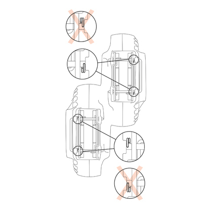
1. คาลิเปอร์เบรกแบบจานเดี่ยว
2. คาลิเปอร์แบบยึดกับที่จานคู่
3. คาลิเปอร์แบบลอยตัวพร้อมแผ่นเบรกยึดแนวรัศมี type 2x60/68
2. คาลิเปอร์แบบยึดกับที่จานคู่
3. คาลิเปอร์แบบลอยตัวพร้อมแผ่นเบรกยึดแนวรัศมี type 2x60/68
ข้อมูลทั้งหมดในชุดคำแนะะนำนี้มีผลกับคาลิเปอร์ทั้งสามประเภท ยกเว้นหากมีระบุไว้เป็นอย่างอื่น
กระบวนการเปลี่ยนชิ้นส่วน
ก่อนเริ่มการเปลี่ยนชิ้นส่วน ชิ้นส่วนอะไหล่ที่ใช้สำหรับเปลี่ยนจะต้องเหมาะสมกับยี่ห้อและรุ่นของรถ
- ถอดล้อออก
- จดบันทึกตำแหน่งต่าง ๆ ของอุปกรณ์ที่ถอดแยกทั้งหมดหรือบางส่วนเพื่อให้ประกอบกลับได้ถูกต้อง

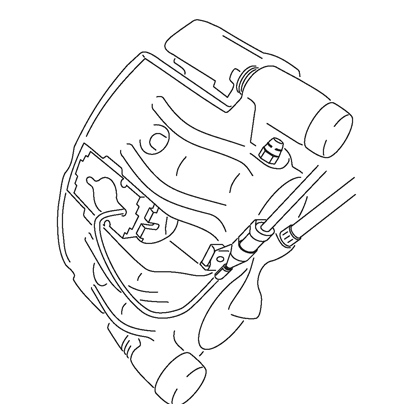
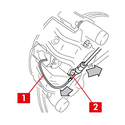
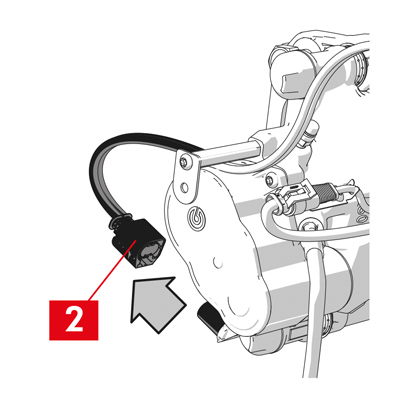
1. ปลดสายไฟแสดงสถานะการสึกหรอ (จุดที่ 1) (ถ้ามี) จากขั้วต่อที่รถ นำออกจากส่วนต่อพ่วงต่าง ๆ ที่รถและที่คาลิเปอร์
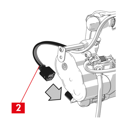
2. สำหรับรุ่นที่ใช้ปิ๊นนิรภัย (จุดที่ 2) ให้นำออกโดยใช้คีม
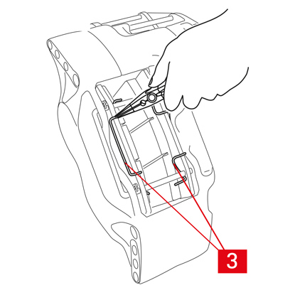
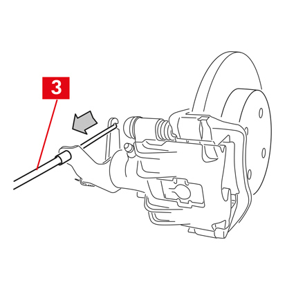
3. สำหรับคาลิเปอร์จานคู่ ให้ถอดสปริง (จุดที่ 3) โดยใช้คีม
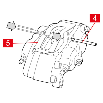
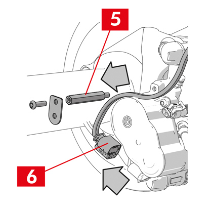
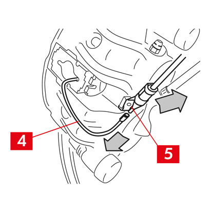
4. ดึงสลัก (จุดที่ 4) โดยใช้ค้อนและตัวขันสลัก ใช้มือดึงออกให้สุดโดยสปริง (จุดที่ 5) จะต้องค้างตำแหน่งอยู่
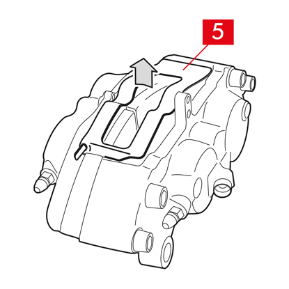
5. ถอดสปริง (จุดที่ 5) ออก ตรวจสอบระดับน้ำมัน เปิดฝาปิดถังน้ำมันเบรก
ระวัง! ขั้นตอนการดึงลูกสูบกลับที่ระบุต่อไปนี้อาจทำให้ระดับน้ำมันเบรกในถังเพิ่มขึ้น ระดับน้ำมันเบรกจะต้องไม่รั่วไหลออกมา เนื่องจากจะทำให้ชิ้นงานสีของรถเสียหาย
คาลิเปอร์แบบยึดกับที่ type A B
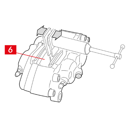
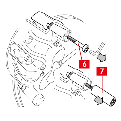
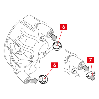
1. ดึงลูกสูบออกเล็กน้อยโดยใช้ตัวถ่างหรือเครื่องมืออื่น ๆ ที่เหมาะสมกดเข้าที่แผ่นเบรก (จุดที่ 6)
การดึงลูกสูบจะต้องมากพอที่จะให้คาลิเปอร์คลายจากจานเบรก
2. นำแผ่นเบรกออกหากโครงสร้างของคาลิเปอร์สามารถทำได้สะดวก ไม่เช่นนั้นให้นำออกหลังจากแยกชิ้นส่วนคาลิเปอร์แล้ว หากต้องการใช้ซ้ำแผ่นเบรก ให้ทำเครื่องหมายกำกับทิศทางการหมุนของจานเบรกไว้โดยใช้ปากกาเมจิค
คาลิเปอร์แบบลอยตัว type C
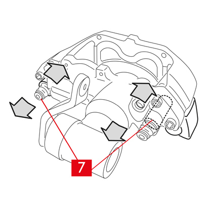
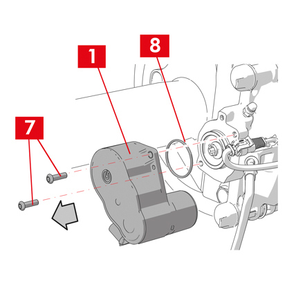
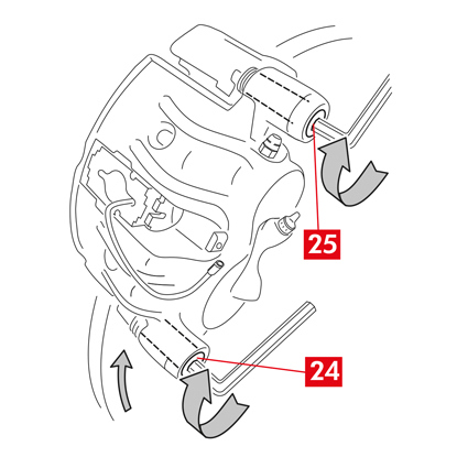
1. นำแผ่นเบรกออกพร้อม ๆ กับเลื่อนตัวคาลิเปอร์ไปมาที่บูชนำแนว (จุดที่ 7) เลื่อนตัวคาลิเปอร์เพื่อดึงแผ่นเบรกเล็กน้อยออกจากจานเบรกเพื่อให้ถอดออกได้ง่าย

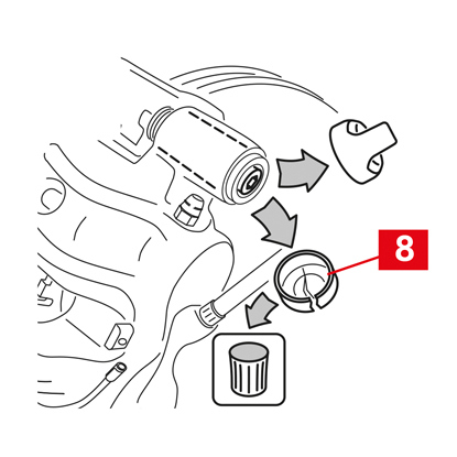
หากเกิดรอยยุบเนื่องจากการสึกหรอของจานเบรกอาจทำให้นำแผ่นเบรกออกได้ยากและจะต้องถอดแยกชิ้นส่วนของคาลิเปอร์:
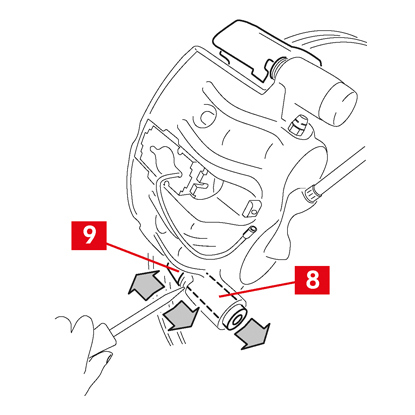
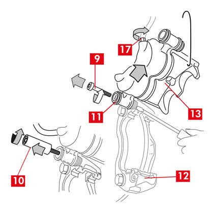
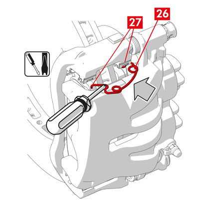
1. ถอนสกรู (จุดที่ 8) โดยใช้กุญแจเลื่อน
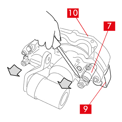
2. ใช้ไขควงสอดเข้าไปที่บูชนำแนวจากบาร่อง
3. นำบูชนำแนวออก (จุดที่ 7) เพื่อให้แยกออกจากแท่นยึดคาลิเปอร์ (จุดที่ 9)
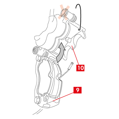
4. แยกคาลิเปอร์ (จุดที่ 1) ออกจากแท่นยึดคาลิเปอร์ (จุดที่ 9) แล้วแขวนไว้กับแชสซีรถโดยใช้ขอเกี่ยวตัว S
5. นำแผ่นเบรกออก
6. หากต้องการใช้ซ้ำแผ่นเบรก ให้ทำเครื่องหมายกำกับทิศทางการหมุนของจานเบรกไว้โดยใช้ปากกาเมจิค
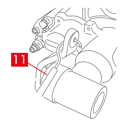
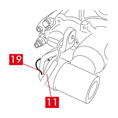
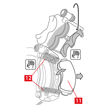
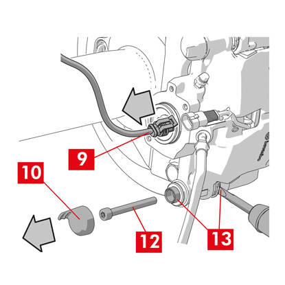
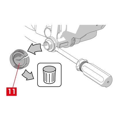
7. สำหรับคาลิเปอร์หลัง (ที่มีกลไกสำหรับการจอด) ให้ปลดสายควบคุมการจอง (จุดที่ 11)
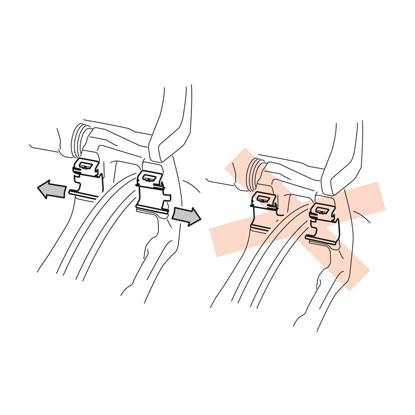
อันตราย! สายน้ำมันเบรกจะต้องเป็นอิสระและไม่ยืดตึง หากมีการยืดสาย อาจทำให้เกิดความเสียหายและน้ำมันเบรกอาจรั่วไหลออกมา
สำหรับคาลิเปอร์ทุกประเภท
1. ปิดฝาปิดถังน้ำมันเบรก
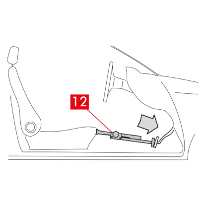
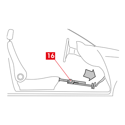
2. ติดตั้งตัวกั้นระยะ (จุดที่ 12) ด้านในห้องโดยสารฝั่งผู้โดยสารระหว่างเบาะนั่งและแป้นเบรกเพื่อให้แป้นเหยียบยังกดค้างอยู่ตลอดการทำงานนี้
คำเตือน! ทั้งนี้เพื่อให้วงจรไฮดรอลิกของเบรกปิดและไม่มีน้ำมันเบรกรั่วไหลออกมมา
ระวัง! ระหว่างกระบวนการทั้งหมดที่ระบุต่อไปนี้ น้ำมันเบรกจะต้องไม่สัมผัสกับชิ้นส่วนของรถที่อาจได้รับความเสียหาย โดยเฉพาะชิ้นส่วนที่เคลือบสี เช็ดคราบน้ำมันที่กระเซ็นหรือรั่วไหลโดยไม่ได้ตั้งใจในทันทีโดยใช้กระดาษเอนกประสงค์แล้วล้างด้วยน้ำเปล่า
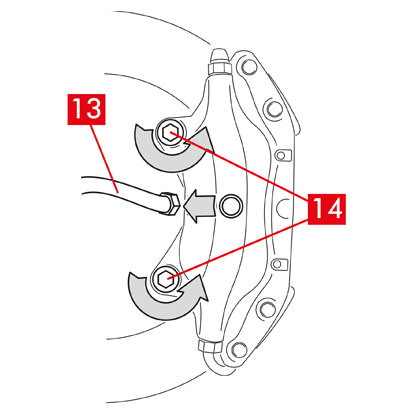
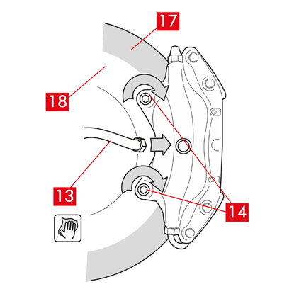
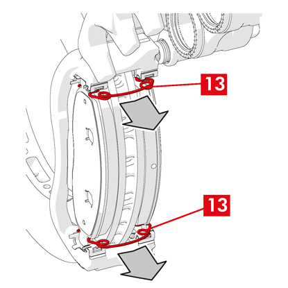
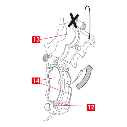
3. คลายสายนำจ่าย (จุดที่ 13) ที่คาลิเปอร์ให้สามารถขันสกรูออกได้สุดด้วยมือ ระวังอย่าให้น้ำมันเบรกรั่วไหลออกมา
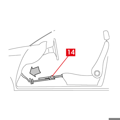
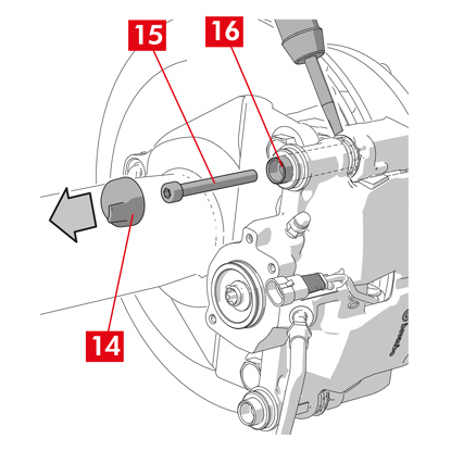
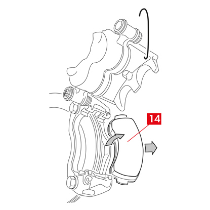
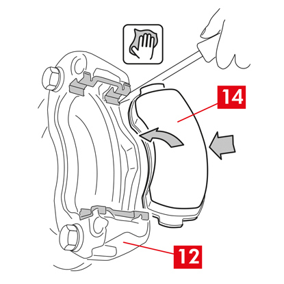
4. ถอดสกรูยึด (จุดที่ 14) โดยใช้ประแจปากตายแล้วถอดคาลิเปอร์จากชุดเพลา
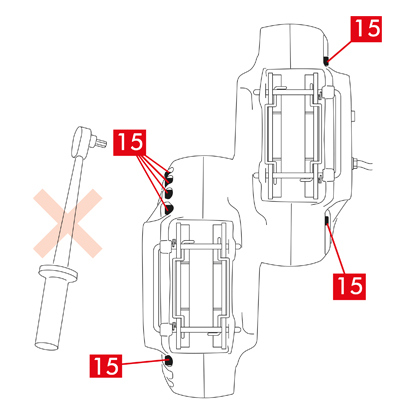
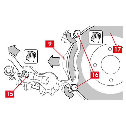
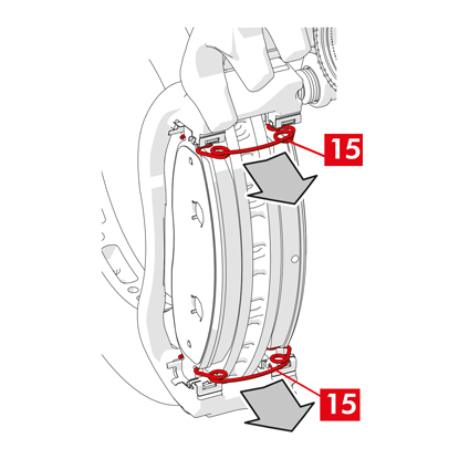
5. ระวัง! สำหรับคาลิเปอร์จานคู่ ให้ถอดแยกเฉพาะสกรูยึดเพลา อย่าถอดสกรู (จุดที่ 15) ที่ยึดประกับคาลิเปอร์เข้าด้วยกัน
6. แยกสายนำจ่าย (จุดที่ 13) ออกมาให้หมดจากคาลิเปอร์
7. เช็ดน้ำมันเบรกที่รั่วไหลออกทันที
8. สายนำจ่ายจะต้องยกสูงเพื่อไม่ให้น้ำมันรั่วไหลโดยไม่ได้ตั้งใจ
9. ดึงคาลิเปอร์ที่จะเปลี่ยนออก
9. ดึงคาลิเปอร์ที่จะเปลี่ยนออก
ขั้นตอนการติดตั้ง
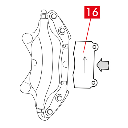
1. ติดตั้งแผ่นเบรก (จุดที่ 16) เข้ากับคาลิเปอร์ใหม่
คำเตือน! ลูกศรที่กำกับที่แผ่นเบรกจะต้องชี้ไปในทิศทางการหมุนของจานเบรก
อันตราย! ติดตั้งแผ่นเบรกโดยให้วัสดุเสียดทานหันเข้าหาจานเบรก
2. คำเตือน! หากโครงสร้างของคาลิเปอร์อำนวย สามารถติดตั้งแผ่นเบรกหลังจากติดตั้งคาลิเปอร์แล้วโดยติดตั้งเข้าไปตรง ๆ หลังจากที่ “ขันแน่นสกรูยึด”
อันตราย! พื้นผิวเสียดทานจะต้องไม่มีคราบน้ำมัน ถ้ามีให้ใช้กระดาษทรายขัดออก
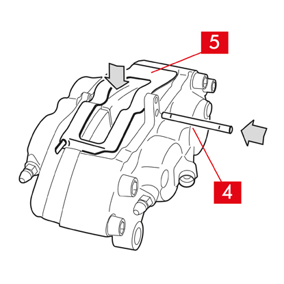
3. ติดตั้งสปริง (จุดที่ 5) และสลัก (จุดที่ 4) กลับเข้าที่ที่ฐานรองที่คาลิเปอร์และแผ่นเบรก สลักจะต้องขันให้สุดโดยใช้ค้อนและตัวขันสลัก
สังเกตทิศทางให้ดีขณะประกอบสปริง
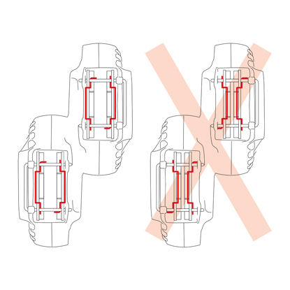
4. ตรวจสอบสปริงว่าตำแหน่งถูกต้อง
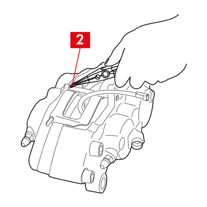
5. สำหรับรุ่นที่มีปิ๊นนิรภัย (จุดที่ 2) ให้ปรับตำแหน่งโดยใช้คีม
6. ตรวจสอบว่าปิ๊นทั้งหมดตำแหน่งถูกต้อง
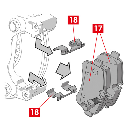
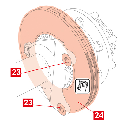
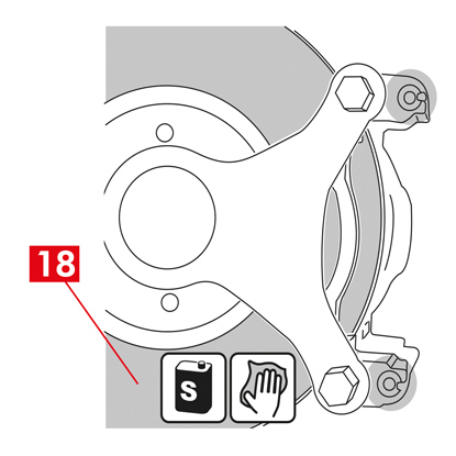
7. ทำความสะอาดพื้นผิวสำหรับเบรก (จุดที่ 17) ที่จานเบรก (จุดที่ 18) โดยใช้ผลิตภัณฑ์ขจัดคราบมัน (เช่น ตัวทำละลาย SE 47)
8. ปรับตำแหน่งคาลิเปอร์ตัวใหม่เข้าที่ชุดเพลา สอดจานเบรก (จุดที่ 18) ไว้ระหว่างแผ่นเบรก
9. ขันแน่นสกรูยึด (จุดที่ 14) โดยใช้ประแจปากตาย ใช้แรงบิดขันแน่นที่ผู้ผลิตรถแนะนำ
หรือใช้แรงบิดขันแน่นที่แนะนำต่อไปนี้
| ประเภทสกรู | M12x1,25 | M12x1,5 | M14x1,5 |
| แรงบิดขันแน่น | 115 Nm | 125 Nm | 180 Nm |
10. ต่อสายไฟแสดงสถานะการสึกหรอเข้าที่ (ถ้ามี) เข้าที่ขั้วต่อที่รถ และกับส่วนต่อพ่วงที่แชสซีและที่คาลิเปอร์
11. ต่อสายจ่ายน้ำมันเบรก (จุดที่ 13) กลับเข้าที่
12. ถอดตัวกั้นระยะที่คุณติดตั้งไว้ก่อนหน้าภายในห้องโดยสารฝั่งผู้โดยสารเพื่อคลายแป้นเบรกออกจานเบรกและทำให้วงจรเปิดอีกครั้ง
13. สำหรับคาลิเปอร์หลัง type C (มีกลไกการจอด) ให้ต่อสายควบคุมการจอง (จุดที่ 11) กลับเข้าที่
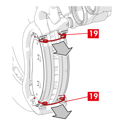
14. ถอดสลักล็อคคันโยก (จุดที่ 19) ออก
15. เข้าเบรกจอดในรถ ทวนซ้ำขั้นตอนหลาย ๆ ครั้งจนกว่าช่วงของกลไกเบรกที่คันโยกจะกลับคืนมาที่ค่าขั้นต่ำ
16. เปิดฝาปิดถังน้ำมันเบรก
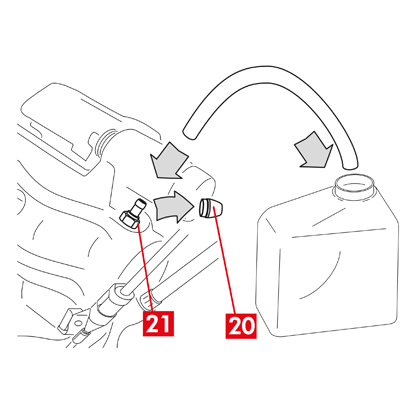
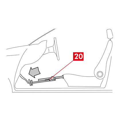
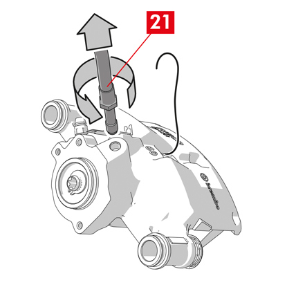
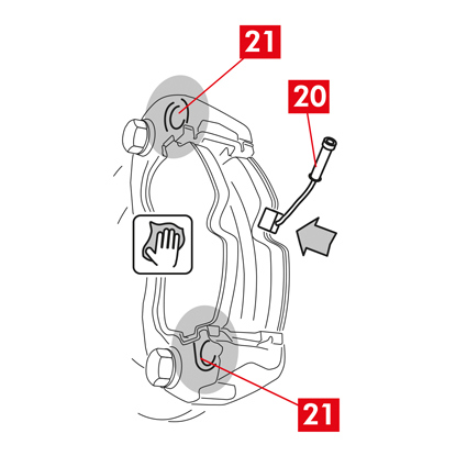
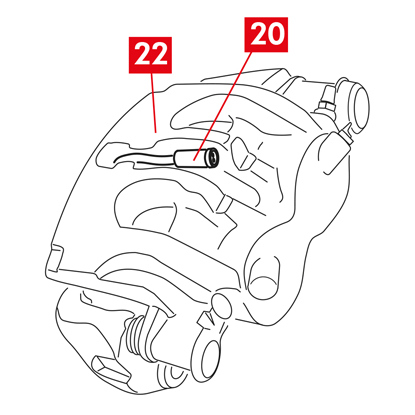
17. ถอดฝาครอบป้องกัน (จุดที่ 20) แล้วต่อท่อใสเข้าที่หัวอุดระบาย (จุดที่ 21) ที่คาลิเปอร์ ปลายสายให้ต่อกับภาชนะรองรับน้ำมัน

18. เปิดหัวอุดระบาย (จุดที่ 21)
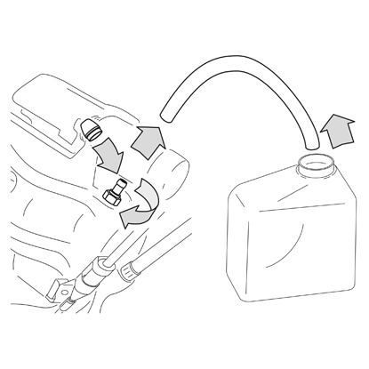
19. กดซ้ำ ๆ ที่แป้นเบรกของรถจนกว่าน้ำมันเบรกจะเริ่มไหลออกจากหัวอุดระบาย
20. กดที่แป้นเหยียบให้ชิดกับหัวอุดระบาย ปล่อยแป้นเหยียบสักครู่ จากนั้นทวนซ้ำขั้นตอนจนกว่าน้ำมันจะไม่มีฟองอากาศออกมาและจนกว่าจะเกิดแรงต้านตามปกติและระยะเคลื่อนของแป้นเบรกกลับเข้าที่
21. ขันแน่นหัวอุดระบายโดยใช้แรงบิดขันแน่นที่ระบุในตาราง:
| หัวอุดระบาย | M6x1 | M6x1 | M6x1 | M6x1 |
| แรงบิดขันแน่น | 5÷7 Nm | 7÷10 Nm | 17÷20 Nm | 18÷22 Nm |
22. ถอดท่อใสออกและปรับตำแหน่งฝาปิดป้องกันที่หัวอุดระบาย
23. ทวนซ้ำขั้นตอนการไล่ระบบสำหรับหัวอุดระบายอื่น ๆ
24. หลังจากไล่ระบบเสร็จสิ้น ให้ดึงลูกสูบกลับภายในคาลิเปอร์ให้สุดโดยใช้เครื่องมือที่เหมาะสม (เช่น เครื่องถ่าง) จากนั้นเติมน้ำมันตามที่ผู้ผลิตแนะนำ
25. ปิดฝาปิดถังน้ำมันเบรก
26. ขณะเครื่องยนต์ทำงาน ให้ใช้แรงกดไปที่แป้นเบรกของรถให้หนักแน่นและตรวจสอบว่าไม่มีน้ำมันรั่วไหลจากคาลิเปอร์หรือไม่มีการสูญเสียแรงดันอย่างผิดปกติในวงจร และไฟเบรกหลังติดสว่าง
อันตราย! หากมีน้ำมันรั่วไหลจากคาลิเปอร์ ให้ทวนซ้ำขั้นตอนทั้งหมดที่ระบุในเอกสารนี้เพื่อระบุสาเหตุและทำการแก้ไขปัญหา
27. ในกรณีของคาลิเปอร์ที่ติดตั้งเบรกจอด ให้ต่อขั้วสายเบรกจอดเข้าที่ฐานรองรับที่คาลิเปอร์ ดึงและปล่อยเบรกจอดภายในห้องโดยสารซ้ำไปมา
28. ประกอบล้อกลับเข้าที่
29. หากเป็นแผ่นเบรกใหม่ ให้ทำการรันอิน ทำตามคำแนะนำที่แจ้งมากับแผ่นเบรกอะไหล่
ต่อไปนี้คือคำแนะนำในการเปลี่ยนคาลิเปอร์เบรก
คาลิเปอร์แบบลอยตัวจะมีสปริงตรงกลาง
คาลิเปอร์แบบลอยตัวที่มีสปริงข้าง 2 หรือ 4 ตัวและสปริงลดแรงบิดคงค้าง
ข้อมูลทั้งหมดในชุดคำแนะะนำนี้มีผลกับคาลิเปอร์ทั้งสองแบบ ยกเว้นหากมีระบุไว้เป็นอย่างอื่น
กระบวนการเปลี่ยนชิ้นส่วน
ก่อนเริ่มการเปลี่ยนชิ้นส่วน ชิ้นส่วนอะไหล่ที่ใช้สำหรับเปลี่ยนจะต้องเหมาะสมกับยี่ห้อและรุ่นของรถ
- ถอดล้อออก
- จดบันทึกตำแหน่งต่าง ๆ ของอุปกรณ์ที่ถอดแยกทั้งหมดหรือบางส่วนเพื่อให้ประกอบกลับได้ถูกต้อง
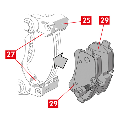
1. ปลดตัวบ่งชี้การสึกหรอ (จุดที่ 1) (ถ้ามี) จากขั้วต่อที่รถ ปลดออกจากแผ่นชิม (จุดที่ 2) ที่ยึดชิ้นส่วนเข้ากับคาลิเปอร์และจากส่วนประกอบต่อพ่วงที่แชสซี
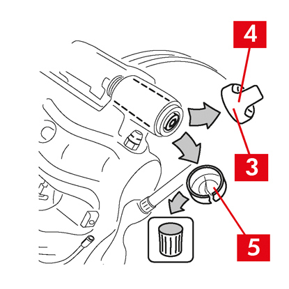
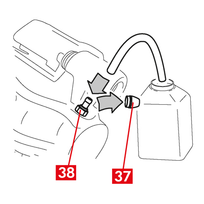
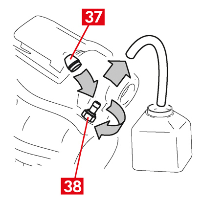
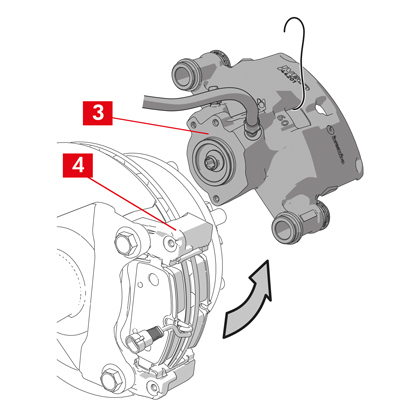
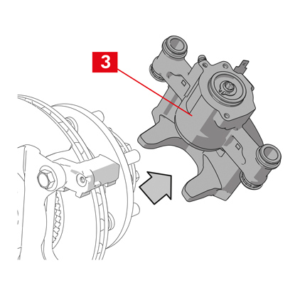
2. ถอดฝาครอบป้องกัน (จุดที่ 3) จากบูชกำหนดตำแหน่ง
3. หากฝาปิดมีขอบ (จุดที่ 4) ให้ปลดฝาปิดโดยดึงที่ขอบ (จุดที่ 4) โดยใช้นิ้ว
4. หากฝาปิดทำจากพลาสติกแข็ง (จุดที่ 5) ให้งัดออกโดยใช้ไขควง การนำฝาปิดออกจะทำให้เกิดความเสียหายได้
คำเตือน! อย่าใช้ฝาพลาสติกแข็งที่ถอดแยกชิ้นส่วนแล้วซ้ำ
ระวัง! บูชกำหนดตำแหน่งสำหรับถอดแยกชิ้นส่วนจะต้องเป็นแบบที่ตัวคาลิเปอร์สามารถบิดได้โดยไม่ทำให้สายจ่ายน้ำมันเบรกยืดตัวออก
คำเตือน! มีบูชกำหนดตำแหน่งอยู่สองประเภทได้แก่
- แบบมีสกรูแยก
- แบบสกรูในตัว
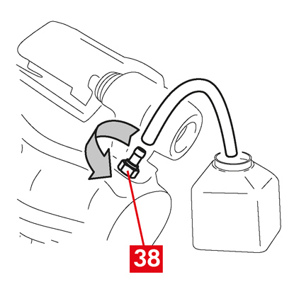
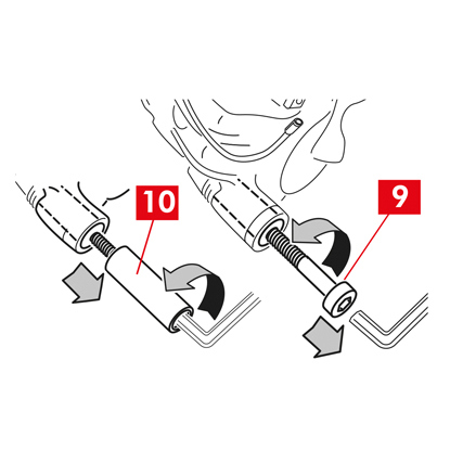
5. คลายและถอดสกรูออก (จุดที่ 6) รวมถึงบูชกำหนดตำแหน่งในตัว (จุดที่ 7) โดยใช้กุญแจเลื่อน
คำเตือน! หากมีแผ่นเบรกที่ยึดกาวกับคาลิเปอร์ ให้ถอดแยกโดยใช้ไขควง
อันตราย! การเปิดตัวคาลิเปอร์อาจทำให้สปริงลดแรงบิดคงค้างกระดอนขึ้นมา
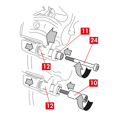
6. ในกรณีที่ใช้บูชกำหนดตำแหน่งที่ไม่ติดตั้งในตัว (จุดที่ 8) ให้ดึงบูชกำหนดตำแหน่งออกจากแท่นยึดคาลิเปอร์ (จุดที่ 9) โดยงัดออกจากบ่ารองโดยใช้ไขควง
7. ขณะเปลี่ยนคาลิเปอร์ที่ล้อหลังที่มีระบบกันสะเทือนและชุดแหนบ บูชกำหนดตำแหน่ง (จุดที่ 8) ทั้งสองตัวจะต้องถูกนำออกเพื่อแยกตัวคาลิเปอร์ (จุดที่ 10) ออกให้พ้นจากแท่นยึดคาลิเปอร์ (จุดที่ 9)
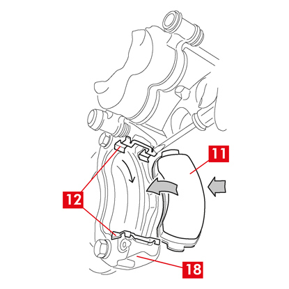
8. ดังตัวคาลิเปอร์ (จุดที่ 10) ออกจากแท่นยึดคาลิเปอร์ (จุดที่ 9) โดยบิดรอบ ๆ บูชกำหนดตำแหน่งอีกตัวจนกระทั่งแผ่นเบรกหลุดออกมาจากแท่นยึดคาลิเปอร์ ยึดตัวคาลิเปอร์เข้ากับแชสซีรถโดยใช้ฐานรองที่เหมาะสม
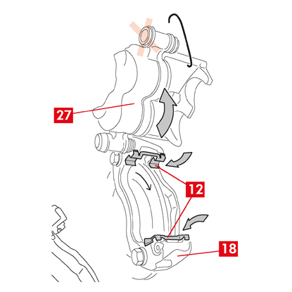
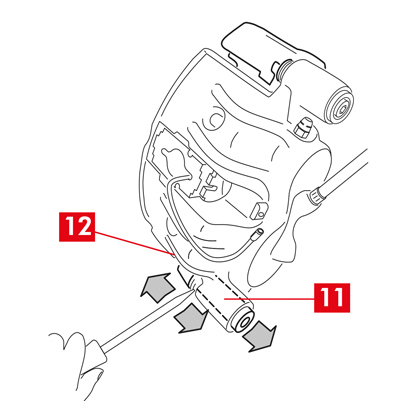
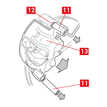
9. ถอดแผ่นเบรก (จุดที่ 11) และสปริง (จุดที่ 12) โดยไม่ทำให้เกิดความเสียหายเพื่อให้คุณสามารถประกอบกลับเข้ากับคาลิเปอร์ตัวใหม่ได้
10. ใช้ปากกาเมจิคกำกับทิศทางของการหมุนของดิสก์ที่แผ่นเบรกเพื่อไม่ให้ประกอบกลับผิดพลาด
11. หากยังอยู่ในตำแหน่ง ให้ถอดสปริงลดแรงบิดคงค้าง (จุดที่ 13)
12. ติดตั้งตัวกั้นระยะ (จุดที่ 14) ด้านในห้องโดยสารฝั่งผู้โดยสารระหว่างเบาะนั่งและแป้นเบรกเพื่อให้แป้นเหยียบยังกดค้างอยู่ตลอดการทำงานนี้
คำเตือน! ทั้งนี้เพื่อให้วงจรไฮดรอลิกของเบรกปิดและไม่มีน้ำมันเบรกรั่วไหลออกมมา
ระวัง! ระหว่างกระบวนการทั้งหมดที่ระบุต่อไปนี้ น้ำมันเบรกจะต้องไม่สัมผัสกับชิ้นส่วนของรถที่อาจได้รับความเสียหาย โดยเฉพาะชิ้นส่วนที่เคลือบสี เช็ดคราบน้ำมันเบรกที่กระเซ็นหรือรั่วไหลโดยไม่ได้ตั้งใจในทันทีโดยใช้กระดาษเอนกประสงค์แล้วล้างด้วยน้ำเปล่า
13. คลายสายนำจ่าย (จุดที่ 15) ที่คาลิเปอร์ให้สามารถขันสกรูออกได้สุดด้วยมือเพื่อป้องกันไม่ให้น้ำมันเบรกรั่วไหลออกมา
14. ถอดสกรูสลักเกลียวยึด (จุดที่ 16) โดยใช้ประแจปากตายแล้วถอดแท่นยึดคาลิเปอร์ (จุดที่ 9) จากแท่นยึดดุม
15. แยกสายนำจ่าย (จุดที่ 15) ออกมาให้หมดจากตัวคาลิเปอร์
16. เช็ดน้ำมันเบรกที่รั่วไหลออกทันที
17. สายนำจ่ายจะต้องยกสูงเพื่อไม่ให้น้ำมันรั่วไหล
18. ในกรณีของคาลิเปอร์ที่ติดตั้งเบรกจอด ให้ปลดสายเบรกจอดจากฐานรองรับที่คาลิเปอร์
19. ดึงคาลิเปอร์ที่จะเปลี่ยนออก
20. ทำความสะอาดพื้นผิวสำหรับเบรก (จุดที่ 17) ที่จานเบรก โดยใช้ผลิตภัณฑ์ขจัดคราบมัน (เช่น ตัวทำละลาย SE47)
กระบวนการติดตั้งคาลิเปอร์
ระวัง! อย่าถอดแยกฝาปิดป้องกันจากรูขาเข้าน้ำมันที่คาลิเปอร์ใหม่จนกว่าคุณจะต่อสายนำจ่ายแล้ว
หล่อลื่นบูชและฝาครอบกันฝุ่นโดยใช้จาระบีที่จัดไว้ให้ก่อนที่จะติดตั้งคาลิเปอร์ใหม่
คำเตือน! EUH210 - สามารถแจ้งขอเอกสารข้อมูลด้านความปลอดภัย
คำเตือน! EUH208 - มีส่วนประกอบของ N-alkylated benzotriazole อาจทำให้เกิดอาการแพ้ได้
1. ถอดฝาครอบป้องกันจากบูช (ถ้ามี)
2. คลายสกรูหรือบูชกำหนดตำแหน่งที่มีสกรูในตัว
3. ในกรณีที่เป็นสกรูแยก ให้ขันสกรูออกให้หมด
4. ดึงตัวคาลิเปอร์ออกจากฐานรองคาลิเปอร์
คำเตือน! เพื่อป้องกันความเสียหายต่อฝาครอบกันฝุ่น ให้ดึงบูชออกจากด้านข้างของฝาครอบ
5. นำฝาครอบออก
6. ทำความสะอาดส่วนประกอบทั้งหมดที่จะติดตั้งให้ทั่ว รวมทั้งบ่ารองบูชและบ่ารองฝาครอบโดยใช้ผลิตภัณฑ์ที่เหมาะสม (เช่น ผ้าชุบหมาด)
7. ทำความสะอาดหน้าแปลนยึดที่แท่นยึดดุม
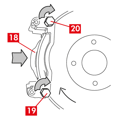
8. กำหนดตำแหน่งแท่นยึดคาลิเปอร์ใหม่ (จุดที่ 18) โดยสอดเข้าไปในจานเบรก
9. สอดสลักเกลียวยึดสองตัว (จุดที่ 19 และ 20)
10. ขันแน่นสลักเกลียวยึดที่ด้านขาเข้าของจานเบรก (จุดที่ 19) (ที่เกียร์เดินหน้า) โดยใช้แรงบิดขันแน่นที่ผู้ผลิตรถแนะนำ
11. ขันแน่นสลักเกลียวยึดตัวที่สอง (จุดที่ 20) (ที่ด้านขาออกของจานเบรก) โดยใช้แรงบิดขันแน่นที่ผู้ผลิตรถแนะนำ
ใช้แรงบิดขันแน่นที่แนะนำต่อไปนี้
| ประเภทสกรู | แรงบิดขันแน่น |
| M12x1,25 | 115 Nm |
| M12x1,5 | 125 Nm |
| M14x1,5 | 180 Nm |
| M16x1,5 | 210 Nm |
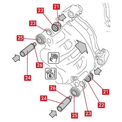
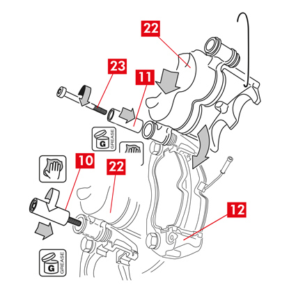
12. ทาจาระบีพื้นผิวด้านในทั้งหมดของฝาครอบ (จุดที่ 21) และแนวหน้าสัมผัส (จุดที่ 22) กับตัวคาลิเปอร์ให้ทั่ว
13. ติดตั้งฝาครอบ (จุดที่ 21) ที่ฐานรอง (จุดที่ 23) ที่ตัวคาลิเปอร์
ระวัง! ใช้นิ้วตรวจสอบว่าฝาครอบสอดเข้าที่ที่ตัวคาลิเปอร์อย่างถูกต้อง
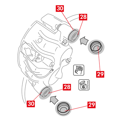
14. ทาจาระบีพื้นผิวด้านนอกของบูช (จุดที่ 24) และบ่ารอง (จุดที่ 25) ที่ตัวคาลิเปอร์ ติดตั้งบูชเข้าที่ตัวคาลิเปอร์จากด้านตรงกันข้ามกับฝาครอบ
15. กดบูช (จุดที่ 24) จนกว่าฝาครอบ (จุดที่ 21) จะประกบเข้ากับบ่ารอง (จุดที่ 26)
16. ขจัดคราบมันส่วนเกินออกไป
17. ประกอบตัวคาลิเปอร์เข้าที่เกลียวแท่นยึดคาลิเปอร์แล้วขันสกรูหรือบูชในตัวที่ด้านขาออกของจานเบรก (เกียร์เดินหน้า)
18. ดังตัวคาลิเปอร์ (จุดที่ 27) ออกจากแท่นยึดคาลิเปอร์ (จุดที่ 18) โดยบิดรอบ ๆ บูชกำหนดตำแหน่งจนกว่าแผ่นเบรกจะเข้าไปที่แท่นยึดคาลิเปอร์ ยึดตัวคาลิเปอร์เข้ากับแชสซีรถโดยใช้ฐานรองที่เหมาะสม
ระวัง! อย่าใช้บ่ารองบูชกำหนดตำแหน่งเป็นจุดยึด
การติดตั้งแผ่นเบรก
1. หากมองเห็นได้ชัดเจน ให้ประกอบสปริงด้านข้าง (จุดที่ 12) เข้าที่แท่นยึดคาลิเปอร์โดยใช้แรงกดที่เหมาะสมเพื่อยึดให้แน่นหนา
2. ในกรณีของคาลิเปอร์แบบสปริงสี่ชิ้น ให้ประกอบสปริงโดยให้ใบพัดหันออกจากแท่นยึดคาลิเปอร์
ระวัง! สังเกตทิศทางในการติดตั้งให้ถูกต้อง
คำเตือน! หากมีแผ่นเบรกมีด้านติดกาว จะต้องประกอบแผ่นเบรกใหม่โดยทำตามคำแนะนำที่จัดมาให้กับแผ่นเบรกอะไหล่ดังกล่าว
ระวัง! แผ่นเบรกที่มีตัวบ่งชี้การสึกหรอให้ประกอบกลับเข้าในตำแหน่งเดิมก่อนที่จะถอดแยกชิ้นส่วน
ระวัง! สังเกตทิศทางในการติดตั้งให้ถูกต้อง
คำเตือน! หากมีแผ่นเบรกมีด้านติดกาว จะต้องประกอบแผ่นเบรกใหม่โดยทำตามคำแนะนำที่จัดมาให้กับแผ่นเบรกอะไหล่ดังกล่าว
ระวัง! แผ่นเบรกที่มีตัวบ่งชี้การสึกหรอให้ประกอบกลับเข้าในตำแหน่งเดิมก่อนที่จะถอดแยกชิ้นส่วน
3. ประกอบแผ่นเบรกกลับเข้าที่ (จุดที่ 11) ที่แท่นยึดคาลิเปอร์ (จุดที่ 18) สำหรับคาลิเปอร์ type B โดยใช้ไขควงเพื่องัดเปิดสปริงด้านข้าง (จุดที่ 12)
คำเตือน! ลูกศรที่กำกับที่แผ่นเบรกจะต้องชี้ไปในทิศทางการหมุนของจานเบรก
อันตราย! ติดตั้งแผ่นเบรกโดยให้วัสดุเสียดทานหันเข้าหาจานเบรก
คำเตือน! ลูกศรที่กำกับที่แผ่นเบรกจะต้องชี้ไปในทิศทางการหมุนของจานเบรก
อันตราย! ติดตั้งแผ่นเบรกโดยให้วัสดุเสียดทานหันเข้าหาจานเบรก
4. ขันสายตัวบ่งชี้การสึกหรอ (จุดที่ 1) ไปตามท่อที่จัดไว้โดยเฉพาะตามนี้:
สำหรับคาลิเปอร์ Type A - ที่สปริง (จุดที่ 28)
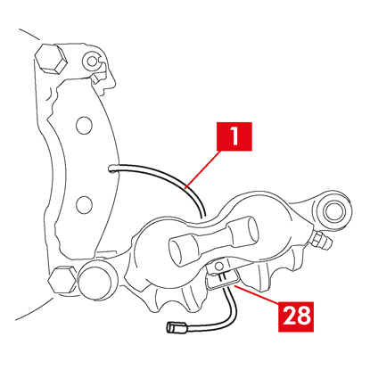
สำหรับคาลิเปอร์ type B - ที่ตัวคาลิเปอร์ (จุดที่ 27)
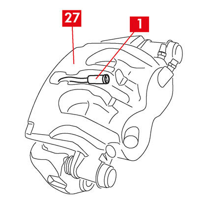
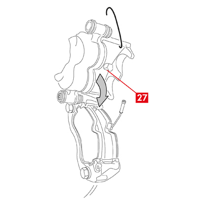
4. ปิดคาลิเปอร์อย่างระมัดระวังโดยบิดที่ตัวคาลิเปอร์ (จุดที่ 27) รอบ ๆ บูชกำหนดตำแหน่งแบบขัน หากมีแผ่นเบรกที่มีด้านกาว ระวังอย่าให้มีการสัมผัสกันระหว่างตัวคาลิเปอร์และแผ่นเบรกก่อนที่จะสิ้นสุดการติดตั้งตัวคาลิเปอร์
ระวัง! ปิดคาลิเปอร์อย่างระมัดระวังโดยฝาครอบป้องกันที่บูชจะต้องไม่ได้รับความเสียหายจากการกระแทกกับแท่นยึดคาลิเปอร์
ระวัง! ปิดคาลิเปอร์อย่างระมัดระวังโดยฝาครอบป้องกันที่บูชจะต้องไม่ได้รับความเสียหายจากการกระแทกกับแท่นยึดคาลิเปอร์
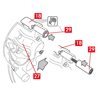
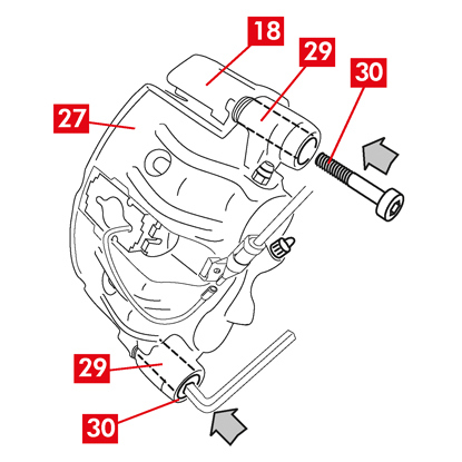
5. ย้ายตัวคาลิเปอร์ (จุดที่ 27)) ไปที่แท่นยึดคาลิเปอร์ (จุดที่ 18)
6. สอดบูชกำหนดตำแหน่ง (จุดที่ 29) เข้าไปใหม่ที่บ่ารองแท่นยึดคาลิเปอร์
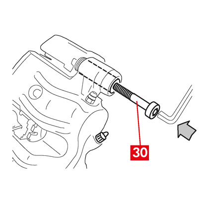
7. สอดและขันสกรูตัวใหม่ (จุดที่ 30) (ถ้ามี)
8. ขณะเปลี่ยนคาลิเปอร์ที่ล้อหลังที่มีระบบกันสะเทือนและแหนบ ตัวคาลิเปอร์ (จุดที่ 27) จะต้องปรับตำแหน่งที่แท่นยึดคาลิเปอร์ (จุดที่ 18) จากนั้นสอดบูชกำหนดตำแหน่งทั้งสองตัว (จุดที่ 29) เข้าไปแล้วสอดและขันแน่นสกรูสองตัวใหม่ (จุดที่ 30) (ถ้ามี)
9. หากยังไม่ได้ขันเข้าไป ให้ขันแน่นสกรูยึดบูชกำหนดตำแหน่งหรือบูชกำหนดตำแหน่งในตัวที่จานเบรกที่ด้านขาเข้าของจานเบรก (ที่เกียร์เดินหน้า) จากนั้นขันแน่นสกรูหรือบูชกำหนดตำแหน่งในตัวอีกตัวที่แรงบิดเท่า ๆ กัน
10. ขันแน่นตามแรงบิดขันแน่นที่ระบุในตารางต่อไปนี้
| ประเภท | แรงบิดขันแน่น | |
| สกรูยึด | (M8 – CH6) | 32 ÷ 36 Nm |
| บูชกำหนดตำแหน่งพร้อมสกรูในตัว | (M8 – CH6) | 32 ÷ 36 Nm |
| บูชกำหนดตำแหน่งพร้อมสกรูในตัว | (M10 – CH8) | 65 ÷ 75 Nm |
อันตราย! ปฏิบัติตามลำดับการขันแน่นที่ระบุ หากไม่ทำตามคำแนะนำอาจทำให้การทำงานของคาลิเปอร์ไม่ถูกต้อง
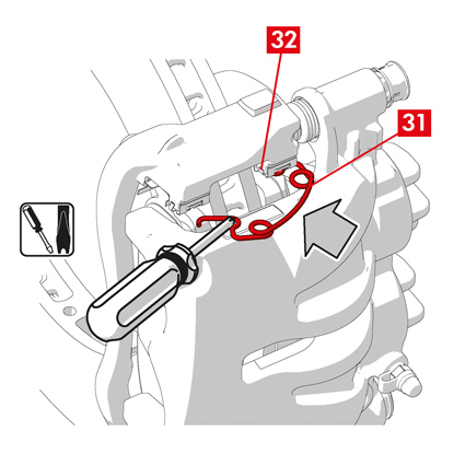
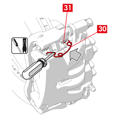
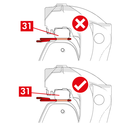
11. ในกรณีที่ใช้สปริงลดแรงบิดคงค้าง (จุดที่ 31) ให้เกี่ยวสปริงไว้ด้านล่างแผ่นรองแผ่นเบรก (จุดที่ 32) แล้วเกี่ยวด้านล่างของแผ่นรองที่แผ่นเบรกอีกตัวโดยใช้ไขควงปลายกลวง
อันตราย! การติดตั้งสปริงไม่ถูกต้องอาจทำให้สปริงง้างออก
ระวัง! สังเกตทิศทางในการติดตั้งให้ถูกต้อง
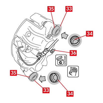
12. ทำความสะอาดชิ้นส่วนอย่างระมัดระวัง (จุดที่ 33) เพื่อไม่ให้เคลื่อนตำแหน่งและประกอบฝาปิดป้องกันใหม่ (จุดที่ 34) โดยอัดจาระบีที่พื้นผิวด้านในและบ่ารองตัวคาลิเปอร์โดยใช้จาระบีที่จัดไว้ให้ในชุดชิ้นส่วนอะไหล่
13. หมุนฝาปิดป้องกัน (จุดที่ 34) เพื่อให้ประกับกับบ่ารองจนแน่น (จุดที่ 35)
14. ประกอบตัวบ่งชี้สถานะการสึกหรอกลับเข้าที่ (ถ้ามี) บริเวณขั้วต่อที่รถ ยึดโดยใช้แรงกดเล็กน้อยที่แผ่นชิมบนคาลิเปอร์ แล้วยึดส่วนต่อพ่วงต่าง ๆ เข้าที่แชสซี
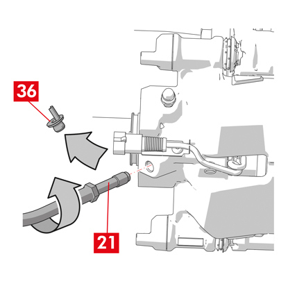
15. ถอดฝาปิดป้องกันจากช่องป้อนน้ำมันเบรก (จุดที่ 36)
16. ต่อสายจ่ายน้ำมันเบรกกลับเข้าที่
17. ถอดตัวกั้นระยะที่คุณติดตั้งไว้ก่อนหน้าภายในห้องโดยสารฝั่งผู้โดยสารเพื่อคลายแป้นเบรกออกจานเบรกและทำให้วงจรไฮดรอลิกเปิดอีกครั้ง
18. เปิดฝาปิดถังน้ำมันเบรก
19. ถอดฝาครอบป้องกัน (จุดที่ 37) แล้วต่อท่อใสเข้าที่หัวอุดระบาย (จุดที่ 38) ที่คาลิเปอร์ ปลายสายให้ต่อกับภาชนะรองรับน้ำมัน
20. เปิดหัวอุดระบาย (จุดที่ 38)
21. กดซ้ำ ๆ ที่แป้นเบรกของรถจนกว่าน้ำมันเบรกจะเริ่มไหลออกจากหัวอุดระบาย
22. กดที่แป้นเหยียบให้ชิดกับหัวอุดระบาย ปล่อยแป้นเหยียบสักครู่ จากนั้นทวนซ้ำขั้นตอนจนกว่าน้ำมันจะไม่มีฟองอากาศออกมาและจนกว่าจะเกิดแรงต้านตามปกติและระยะเคลื่อนของแป้นเบรกกลับเข้าที่
23. ขันแน่นหัวอุดระบายโดยใช้แรงบิดขันแน่นที่ระบุในตาราง:
| หัวอุดระบาย | M6x1 | M8x1,25 | M10x1 | M12x1 |
| แรงบิดขันแน่น | 5÷7 Nm | 7÷10 Nm | 17÷20 Nm | 18÷22 Nm |
24. ถอดท่อใสออกและปรับตำแหน่งฝาปิดป้องกันที่หัวอุดระบาย
25. ทวนซ้ำขั้นตอนการไล่ระบบสำหรับหัวอุดระบายอื่น ๆ
26. หลังจากไล่ระบบเสร็จสิ้น ให้ดึงลูกสูบกลับภายในคาลิเปอร์ให้สุดโดยใช้เครื่องมือที่เหมาะสม (เช่น เครื่องถ่าง) จากนั้นเติมน้ำมันตามที่ผู้ผลิตแนะนำ
27. ปิดฝาปิดถังน้ำมันเบรก
28. ขณะเครื่องยนต์ทำงาน ให้ใช้แรงกดไปที่แป้นเบรกของรถให้หนักแน่นและตรวจสอบว่าไม่มีน้ำมันรั่วไหลจากคาลิเปอร์หรือไม่มีการสูญเสียแรงดันอย่างผิดปกติในวงจร และไฟเบรกหลังติดสว่าง
อันตราย! หากมีน้ำมันรั่วไหลจากคาลิเปอร์ ให้ทวนซ้ำขั้นตอนทั้งหมดที่ระบุในเอกสารนี้เพื่อระบุสาเหตุและทำการแก้ไขปัญหา
29. ในกรณีของคาลิเปอร์ที่ติดตั้งเบรกจอด ให้ต่อขั้วสายเบรกจอดเข้าที่ฐานรองรับที่คาลิเปอร์
30. ดึงและปล่อยเบรกจอดภายในห้องโดยสารซ้ำไปมา
31. ประกอบล้อกลับเข้าที่
32. หากเป็นแผ่นเบรกใหม่ ให้ทำการรันอิน ทำตามคำแนะนำที่แจ้งมากับแผ่นเบรกอะไหล่
ต่อไปนี้คือคำแนะนำในการเปลี่ยนส่วนประกอบต่าง ๆ สำหรับคาลิเปอร์แบบลอยตัวในรถยนต์ใช้งานเชิงพาณิชย์ (type ECS53 และ ECS60) ซึ่งใช้กลไกจอดไฟฟ้าร่วมด้วย ได้แก่
1. ชุดแอคชูเอเตอร์
2. แผ่นเบรก
3. ตัวคาลิเปอร์ (ไม่รวมแผ่นเบรกและแท่นยึดคาลิเปอร์)
4. แท่นยึดคาลิเปอร์
2. แผ่นเบรก
3. ตัวคาลิเปอร์ (ไม่รวมแผ่นเบรกและแท่นยึดคาลิเปอร์)
4. แท่นยึดคาลิเปอร์
คำเตือน! อ่านเอกสารชุดนี้ก่อนทำการเปลี่ยนชิ้นส่วนอะไหล่ในชุดผลิตภัณฑ์จัดจำหน่าย ทำตามขั้นตอนที่กำหนดในการเปลี่ยนชิ้นส่วนอะไหล่หรือชิ้นส่วนที่จัดมาให้ใช้ชุดผลิตภัณฑ์จัดจำหน่ายเท่านั้น
กระบวนการเปลี่ยนชิ้นส่วน
ก่อนเริ่มการเปลี่ยนชิ้นส่วน ชิ้นส่วนอะไหล่ที่ใช้สำหรับเปลี่ยนจะต้องเหมาะสมกับยี่ห้อและรุ่นของรถ
คำเตือน! ในกรณีที่เกิดปัญหากับระบบไฟฟ้า ให้ถอดแยกแอคชูเอเตอร์แล้วดึงลูกสูบกลับและหมนุสกรูทอร์กซ์ตามเข็มนาฬิกาโดยใช้ประแจที่เหมาะสม
- จดบันทึกตำแหน่งต่าง ๆ ของอุปกรณ์ที่ถอดแยกทั้งหมดหรือบางส่วนเพื่อให้ประกอบกลับได้ถูกต้อง
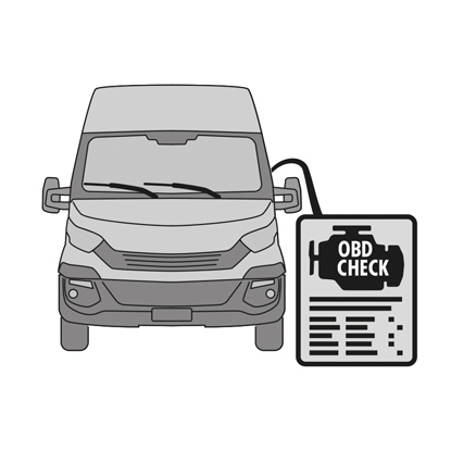
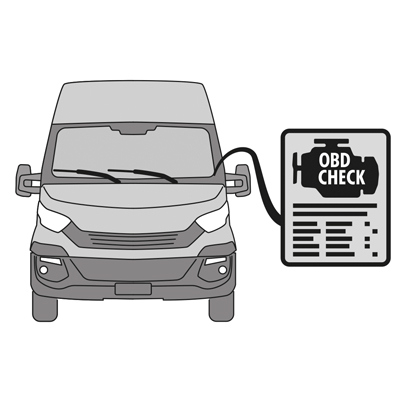
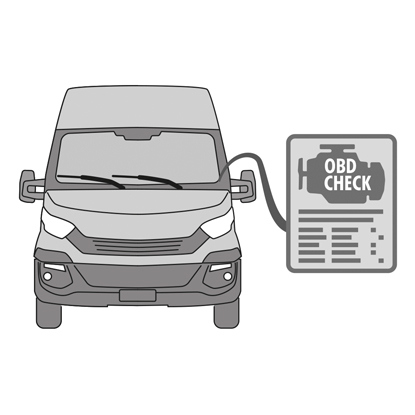
1. เชื่อมต่อเครื่องมือวินิจฉัยปัญหา (On Board Diagnosis - OBD) เข้ากับรถแล้วตั้งค่าในโหมดดูแลรักษาตามที่ระบุโดยผู้ผลิตรถ
ระวัง! ชิ้นส่วนอะไหล่จะต้องรองรับซอฟต์แวร์ของรถ
2. ถอดล้อออก
3. ปลดสายจ่ายไฟของชุดแอคชูเอเตอร์จากปลอกสาย
4. สำหรับคาลิเปอร์ type ECS60 ให้คลายแล้วถอดปลอกสาย (จุดที่ 5) ออก
5. ปลดสายจ่ายไฟ (จุดที่ 6) จากชุดแอคชูเอเตอร์
คำเตือน! หัวต่ออาจมีล็อคนิรภัยติดตั้งอยู่
คำเตือน! หัวต่ออาจมีล็อคนิรภัยติดตั้งอยู่
การถอดประกอบชุดแอคชูเอเตอร์
คำเตือน! ทำการถอดแยกชุดแอคชูเอเตอร์เฉพาะในกรณีที่มีชิ้นส่วนอะไรจัดแยกไว้เฉพาะ
1. คลายสกรูยึด (จุดที่ 7) จากชุดแอคชูเอเตอร์ (จุดที่ 1)
2. ถอดชุดแอคชูเอเตอร์ (จุดที่ 1)
3. ถอดซีล (จุดที่ 8)
การถอดแยกแผ่นเบรก
ระวัง! อย่าทำให้ส่วนประกอบได้รับความเสียหายหากต้องการนำไปใช้ซ้ำ
อันตราย! อย่าทำให้สายจ่ายน้ำมันเบรกยืดตัว
อันตราย! อย่าทำให้สายจ่ายน้ำมันเบรกยืดตัว
1. ปลดตัวบ่งชี้การสึกหรอ (จุดที่ 9) (ถ้ามี) จากขั้วต่อที่รถ ปลดออกจากแผ่นชิมที่ยึดชิ้นส่วนเข้ากับคาลิเปอร์และจากส่วนประกอบต่อพ่วงที่แชสซี
2. ถอดฝาครอบป้องกัน (จุดที่ 10) จากบูชสำรอง (ด้านขาออกของจานเบรกหมุนไปด้านหน้า)
3. หากฝาปิดทำจากพลาสติกแข็ง (จุดที่ 11) ให้งัดออกโดยใช้ไขควง การนำฝาปิดออกจะทำให้เกิดความเสียหายได้
คำเตือน! อย่าใช้ฝาพลาสติกแข็งที่ถอดแยกชิ้นส่วนแล้วซ้ำ
4. คลายและถอดสกรู (จุดที่ 12)
5. สำหรับคาลิเปอร์ type ECS60 ให้ใช้ไขควงเพื่องัดบูชออกจากร่องเพื่อคลายชิ้นส่วนออกจากแท่นยึดคาลิเปอร์
6. ถอดฝาครอบป้องกัน (จุดที่ 14) จากบูชหลัก (ด้านขาเข้าของจานเบรกหมุนไปด้านหน้า)
7. คลายสกรูหลัก (จุดที่ 15) ให้สุดแล้วนำออก
คำเตือน! ใช้ไขควงเพื่องัดบูชกำหนดตำแหน่งออกจากแนวร่อง
8. ถอดบูชกำหนดตำแหน่งหลัก (จุดที่ 16) ให้คลายตัวออกจากแท่นยึดคาลิเปอร์
9. ดึงตัวคาลิเปอร์ (จุดที่ 3) ออกจากแท่นยึดคาลิเปอร์ (จุดที่ 4) ระวังอย่าให้สายจ่ายน้ำมันเบรกยืดตัว
10. ยึดตัวคาลิเปอร์เข้ากับแชสซีรถโดยใช้ฐานรองที่เหมาะสม
ระวัง! อย่าใช้บ่ารองบูชเป็นจุดยึด
11. ถอดแผ่นเบรก (จุดที่ 17) และสปริง (จุดที่ 18) โดยไม่ทำให้เกิดความเสียหายเพื่อให้คุณสามารถประกอบกลับเข้ากับคาลิเปอร์ตัวใหม่ได้
12. หากยังอยู่ในตำแหน่ง ให้ถอดสปริงลดแรงบิดคงค้าง (จุดที่ 19)
คำเตือน! เพื่อให้ติดตั้งแผ่นเบรกเดิมกลับเข้าที่ได้ถูกต้อง ให้กำกับตำแหน่งลูกศร (หากไม่มีแสดงไว้) ไว้ที่แผ่นเบรกโดยใช้ปากกาเมจิคเพื่อระบุทิศทางการหมุนของจานเบรก
การถอดแยกตัวคาลิเปอร์
1. ติดตั้งตัวกั้นระยะ (จุดที่ 20) ด้านในห้องโดยสารฝั่งผู้โดยสารระหว่างเบาะนั่งและแป้นเบรกเพื่อให้แป้นเหยียบยังกดค้างอยู่ตลอดการทำงานนี้
คำเตือน! ทั้งนี้เพื่อให้วงจรไฮดรอลิกของเบรกปิดและไม่มีน้ำมันเบรกรั่วไหลออกมมา
ระวัง! ระหว่างกระบวนการทั้งหมดที่ระบุต่อไปนี้ น้ำมันเบรกจะต้องไม่สัมผัสกับชิ้นส่วนของรถที่อาจได้รับความเสียหาย โดยเฉพาะชิ้นส่วนที่เคลือบสี เช็ดคราบน้ำมันเบรกที่กระเซ็นหรือรั่วไหลโดยไม่ได้ตั้งใจในทันทีโดยใช้กระดาษเอนกประสงค์แล้วล้างด้วยน้ำเปล่า
2. คลายสายนำจ่าย (จุดที่ 21) ที่คาลิเปอร์ให้สามารถขันสกรูออกได้สุดด้วยมือเพื่อป้องกันไม่ให้น้ำมันเบรกรั่วไหลออกมา
3. แยกสายนำจ่าย (จุดที่ 21) ออกมาให้หมดจากตัวคาลิเปอร์
4. เช็ดน้ำมันเบรกที่รั่วไหลออกทันที
5. สายนำจ่ายจะต้องยกสูงเพื่อไม่ให้น้ำมันรั่วไหล
6. ดึงตัวคาลิเปอร์ (จุดที่ 3) ออก
การถอดแยกแท่นยึดคาลิเปอร์
ระวัง! ระหว่างการถอดแยกชิ้นส่วน แท่นยึดคาลิเปอร์จะต้องอยู่ในตำแหน่งที่ถูกต้องเพื่อไม่ให้ร่วงหล่นลงมาโดยไม่ตั้งใจ
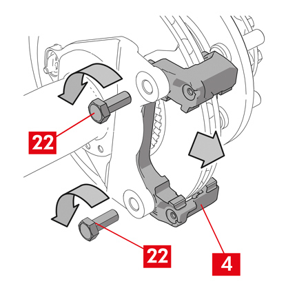
1. คลายสกรูยึด (จุดที่ 22)
2. ถอดแท่นยึดคาลิเปอร์ (จุดที่ 4) จากแท่นยึดดุม
ขั้นตอนการติดตั้ง
ประกอบชิ้นส่วนอะไหล่ใหม่กลับเข้าที่
1. ทำความสะอาดส่วนประกอบทั้งหมดที่จะติดตั้งให้ทั่ว (ไม่ว่าจะเป็นชิ้นส่วนใหม่หรือที่ถอดแยกออกมา) รวมทั้งบ่ารองบูชและบ่ารองสปริงโดยใช้ผลิตภัณฑ์ที่เหมาะสม (เช่น ผ้าชุบหมาด)
อันตราย! ส่วนรปะกอบจะต้องอยู่ในสภาพสมบูรณ์ เปลี่ยนชิ้นส่วนใหม่หากพบความเสียหาย
2. ทำความสะอาดหน้าแปลนยึด (จุดที่ 23) ที่แท่นยึดดุม
3. ทำความสะอาดพื้นผิวสำหรับเบรก (จุดที่ 24) ที่จานเบรก โดยใช้ผลิตภัณฑ์ขจัดคราบมัน (เช่น ตัวทำละลาย SE47)
การประกอบแท่นยึดคาลิเปอร์
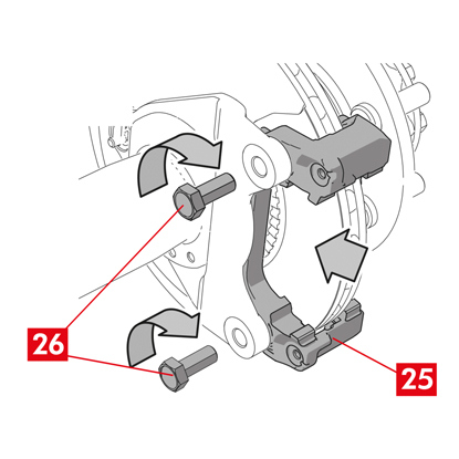
1. ติดตั้งแท่นยึดคาลิเปอร์ (จุดที่ 25) ที่แท่นยึดดุม
2. ติดตั้งและขันแน่นสกรูยึด (จุดที่ 26) ตามแรงบิดที่ผู้ผลิตรถแนะนำ
การประกอบแผ่นเบรกและตัวคาลิเปอร์
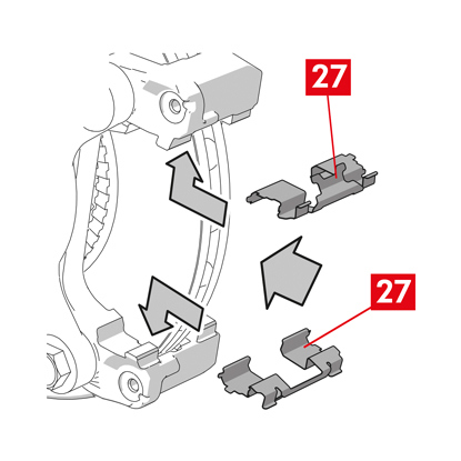
1. ประกอบสปริง (จุดที่ 27) กลับเข้าที่ โดยจัดวางในตำแหน่งที่ถูกต้องบริเวณบ่ารอง
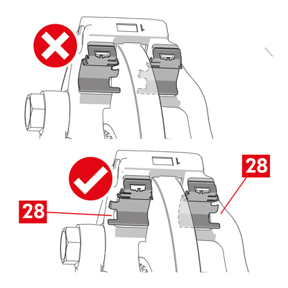
2. สำหรับคาลิเปอร์ type ECS52 แบบสปริงสี่ชิ้น ให้ประกอบสปริงโดยให้ใบพัด (จุดที่ 28) หันออกจากแท่นยึดคาลิเปอร์
คำเตือน! หากมีแผ่นเบรกมีด้านติดกาว จะต้องประกอบแผ่นเบรกใหม่โดยทำตามคำแนะนำที่จัดมาให้กับแผ่นเบรกอะไหล่ดังกล่าว
ระวัง! แผ่นเบรกที่มีตัวบ่งชี้การสึกหรอให้ประกอบกลับเข้าในตำแหน่งเดิมก่อนที่จะถอดแยกชิ้นส่วน
อันตราย! ติดตั้งแผ่นเบรกโดยให้วัสดุเสียดทานหันเข้าหาจานเบรก
3. ประกอบแผ่นเบรกกลับเข้าที่ (จุดที่ 29) ที่แท่นยึดคาลิเปอร์ (จุดที่ 25) โดยใช้ไขควงเพื่องัดเปิดสปริงด้านข้าง (จุดที่ 27)
4. ในกรณีที่ใช้สปริงลดแรงบิดคงค้าง (จุดที่ 30) ให้เกี่ยวสปริงไว้ด้านล่างแผ่นรองแผ่นเบรก (จุดที่ 31) แล้วเกี่ยวด้านล่างของแผ่นรองที่แผ่นเบรกอีกตัวโดยใช้ไขควงปลายกลวง
อันตราย! การติดตั้งสปริงไม่ถูกต้องอาจทำให้สปริงง้างออก
อันตราย! การติดตั้งสปริงไม่ถูกต้องอาจทำให้สปริงง้างออก
ระวัง! สังเกตทิศทางในการติดตั้งให้ถูกต้อง
ระวัง! หากตัวคาลิเปอร์เป็นชิ้นส่วนใหม่ อย่าถอดแยกฝาปิดป้องกันจากรูขาเข้าน้ำมันที่คาลิเปอร์ใหม่จนกว่าคุณจะต่อสายนำจ่ายแล้ว
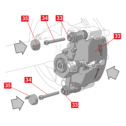
6. ติดตั้งตัวคาลิเปอร์ (จุดที่ 32) โดยสอดเข้าไปที่จานเบรกเพื่อให้บูชกำหนดตำแหน่งรับกับช่องที่แท่นยึดคาลิเปอร์
ระวัง! อย่าทำให้ฝาครอบเสียหาย
7. กดบูชกำหนดตำแหน่ง (จุดที่ 33) เข้าที่บ่ารองบนแท่นยึดคาลิเปอร์
8. สอดและขันแน่นสกรู (จุดที่ 34) โดยใช้แรงบิดขันแน่นที่ 32 ÷ 36 Nm
9. ติดตั้งฝาครอบ (จุดที่ 35)
ระวัง! ก่อนถอดฝาครอบป้องกัน จุดจ่ายจะต้องอยู่ให้สูงมากที่สุดเพื่อไม่ให้น้ำมันเบรกด้านในคาลิเปอร์รั่วไหลออกมา
10. ประกอบสายตัวบ่งชี้การสึกหรอกลับเข้าที่ (ถ้ามี) เข้ากับขั้วต่อที่รถ ยึดโดยใช้แรงกดที่แผ่นชิมบนคาลิเปอร์เล็กน้อย (ถ้ามี) แล้วยึดชิ้นส่วนต่อพ่วงต่าง ๆ ที่แชสซี
การต่อสายจ่ายน้ำมันเบรก
1. ถอดฝาครอบป้องกัน (จุดที่ 36) จากช่องป้อนน้ำมันเบรก
2. ต่อสายจ่ายน้ำมันเบรก (จุดที่ 21) กลับเข้าที่
3. ถอดตัวกั้นระยะที่คุณติดตั้งไว้ก่อนหน้าภายในห้องโดยสารฝั่งผู้โดยสารเพื่อคลายแป้นเบรกออกจากเบรกและทำให้วงจรเปิดอีกครั้ง
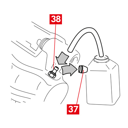
4. ถอดฝาครอบป้องกัน (จุดที่ 37) จากหัวอุดระบาย (จุดที่ 38)
5. ต่อท่อใสเข้าที่หัวอุดระบาย (จุดที่ 38) ที่คาลิเปอร์ ปลายสายให้ต่อกับภาชนะรองรับน้ำมัน
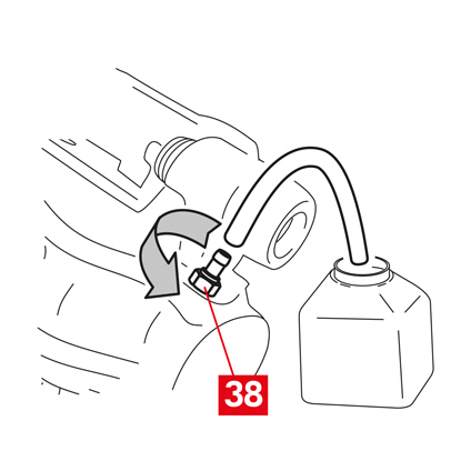
6. เปิดหัวอุดระบาย (จุดที่ 38)
7. กดซ้ำ ๆ ที่แป้นเบรกของรถจนกว่าน้ำมันเบรกจะเริ่มไหลออกจากหัวอุดระบาย
8. กดที่แป้นเหยียบให้ชิดกับหัวอุดระบาย ปล่อยแป้นเหยียบสักครู่ จากนั้นทวนซ้ำขั้นตอนจนกว่าน้ำมันจะไม่มีฟองอากาศออกมาและจนกว่าจะเกิดแรงต้านตามปกติและระยะเคลื่อนของแป้นเบรกกลับเข้าที่
9. ขันแน่นหัวอุดระบาย (จุดที่ 38) โดยใช้แรงบิดขันแน่นตามที่ระบุในตารางต่อไปนี้
| ประเภทหัวอัดไล่ | M10x1 |
| แรงบิดขันแน่น | 12÷16 Nm |
10. ถอดท่อใส
11. ทวนซ้ำขั้นตอนการไล่ระบบสำหรับหัวอุดระบายอื่น ๆ
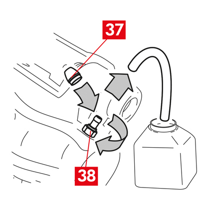
12. ปรับตำแหน่งฝาครอบป้องกัน (จุดที่ 37)
13. หลังจากไล่ระบบเสร็จสิ้น ให้ดึงลูกสูบกลับภายในคาลิเปอร์ให้สุดโดยใช้เครื่องมือที่เหมาะสม (เช่น เครื่องถ่าง) จากนั้นเติมน้ำมันตามที่ผู้ผลิตแนะนำ
14. ขณะเครื่องยนต์ทำงาน ให้ใช้แรงกดไปที่แป้นเบรกของรถให้หนักแน่นและตรวจสอบว่าไม่มีน้ำมันรั่วไหลจากคาลิเปอร์หรือไม่มีการสูญเสียแรงดันอย่างผิดปกติในวงจร และไฟเบรกหลังติดสว่าง
อันตราย! หากมีน้ำมันรั่วไหลจากคาลิเปอร์ ให้ทวนซ้ำขั้นตอนทั้งหมดที่ระบุในเอกสารนี้เพื่อระบุสาเหตุและทำการแก้ไขปัญหา
การติดตั้งชุดแอคชูเอเตอร์
คำเตือน! ชุดแอคชูเอเตอร์อาจจำหน่ายโดยติดตั้งมากับตัวคาลิเปอร์อยู่แล้ว
ประกอบชิ้นส่วนอะไหล่ใหม่กลับเข้าที่
- ทำความสะอาดส่วนประกอบที่คุณถอดไว้ก่อนหน้าก่อนที่จะประกอบกลับเข้าที่
ระวัง! ใช้สกรูใหม่กับน้ำยาล็อคเกลียวทุกครั้ง ติดตั้งซีลใหม่ทุกครั้ง
อันตราย! ส่วนรปะกอบจะต้องอยู่ในสภาพสมบูรณ์ เปลี่ยนชิ้นส่วนใหม่หากพบความเสียหาย
1. ทำความสะอาดพื้นผิวสัมผัสที่คาลิเปอร์และชุดแอคชูเอเตอร์
2. ขจัดคราบน้ำยาล็อคเกลียวจากบ่ารองสกรูแบบเกลียว
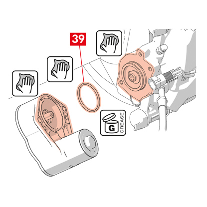
3. ทำความสะอาดและหล่อลื่นซีล (จุดที่ 39) โดยใช้จาระบีที่จัดมาให้
4. หล่อลื่นเส้นผ่านศูนย์กลางด้านในของคัปลิงชุดแอคชูเอเตอร์โดยใช้จาระบีที่จัดมาให้
คำเตือน! EUH210 - สามารถแจ้งขอเอกสารข้อมูลด้านความปลอดภัย
คำเตือน! EUH208 - มีส่วนประกอบของ N-alkylated benzotriazole อาจทำให้เกิดอาการแพ้ได้
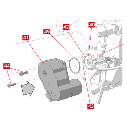
5. ติดตั้งซีล (จุดที่ 39) ที่บ่ารอง (จุดที่ 40) ที่ตัวคาลิเปอร์
6. ติดตั้งชุดแอคชูเอเตอร์ (จุดที่ 41) ที่ทอร์กซ์สกรู (จุดที่ 42) ที่ตัวคาลิเปอร์
7. หมุนชุดแอคชูเอเตอร์ (จุดที่ 41) เพื่อให้ช่อง (จุดที่ 43) ของสกรูยึด (จุดที่ 44) สอดรับกับตำแหน่งติดตั้งเดิม
ระวัง! หลีกเลี่ยงการบีบอัดซีล (จุดที่ 39) ขณะประกอบชุดแอคชูเอเตอร์ที่ตัวคาลิเปอร์
8. สอดและขันแน่นสกรูยึด (จุดที่ 44) โดยใช้แรงบิดขันแน่น 7 ÷ 10 Nm
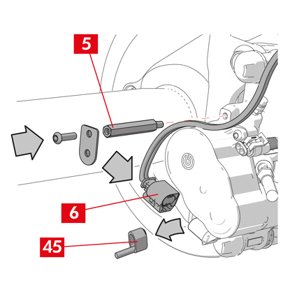
9. ถอดฝาครอบป้องกัน (จุดที่ 45) (ถ้ามี) จากนั้นต่อสายจ่ายไฟ (จุดที่ 6)
10. หากถอดแยกไว้ก่อนหน้านี้ ให้ขันสกรูปลอกสาย (จุดที่ 5)
11. ยึดสายจ่ายไฟชุดแอคชูเอเตอร์ (จุดที่ 6) เข้ากับปลอกสาย (จุดที่ 5)
ขั้นตอนสุดท้าย
1. ประกอบล้อกลับเข้าที่
2. ทำการรีเซ็ต (ตรวจสอบงานประกอบ)
3. ในกรณีที่จำเป็น ให้รีเซ็ตตัวนับจำนวน (รีเซ็ตตัวนับจำนวนภายใน) ตามที่ผู้ผลิตรถระบุ
4. ทำการรันอินแผ่นเบรกตามที่ผู้ผลิตรถกำหนด
5. ปลดอุปกรณ์วินิจฉัยปัญหา (On Board Diagnosis – OBD)
ต่อไปนี้เป็นคำแนะนำสำหรับเปลี่ยนตัวคาลิเปอร์สำหรับคาลิเปอร์แบบลอยตัวที่ติดตั้งสปริงด้านข้าง 2 หรือ 4 ตัว รวมทั้งสปริงลดแรงบิดคงค้าง
ในกรณีที่เปลี่ยนเฉพาะสกรูยึด ให้ดูเฉพาะคำแนะนำสำหรับส่วนประกอบที่เกี่ยวข้อง
กระบวนการเปลี่ยนชิ้นส่วน
ก่อนเริ่มการเปลี่ยนชิ้นส่วน ชิ้นส่วนอะไหล่ที่ใช้สำหรับเปลี่ยนจะต้องเหมาะสมกับยี่ห้อและรุ่นของรถ
- จดบันทึกตำแหน่งต่าง ๆ ของอุปกรณ์ที่ถอดแยกทั้งหมดหรือบางส่วนเพื่อให้ประกอบกลับได้ถูกต้อง
- ถอดล้อออก
สำหรับคาลิเปอร์ ECS
คำเตือน! ในกรณีที่เกิดปัญหากับระบบไฟฟ้า ให้ถอดแยกชุดแอคชูเอเตอร์ (จุดที่ 5) แล้วดึงลูกสูบกลับและหมนุสกรูทอร์กซ์ตามเข็มนาฬิกาโดยใช้ประแจที่เหมาะสม

1. เชื่อมต่อเครื่องมือวินิจฉัยปัญหา (On Board Diagnosis - OBD) เข้ากับรถแล้วตั้งค่าในโหมดดูแลรักษาตามที่ระบุโดยผู้ผลิตรถ
ระวัง! หากไม่ดำเนินการตามนี้ จะไม่สามารถรั้งลูกสูบกลับโดยใช้เครื่องถ่างหรือเครื่องมืออื่น ๆ ที่เหมาะสม
ระวัง! ชิ้นส่วนอะไหล่จะต้องรองรับซอฟต์แวร์ของรถ
2. ปลดสายจ่ายไฟ (จุดที่ 2) จากชุดแอคชูเอเตอร์
คำเตือน! หัวต่ออาจมีล็อคนิรภัยติดตั้งอยู่
สำหรับคาลิเปอร์ทุกประเภท
1. สำหรับคาลิเปอร์ที่มีเบรกจอด ให้แยกสายควบคุม (จุดที่ 3) จากคาลิเปอร์
2. ปลดตัวบ่งชี้การสึกหรอ (จุดที่ 4) (ถ้ามี) จากขั้วต่อที่รถ ปลดออกจากแผ่นชิม (จุดที่ 5) ที่ยึดชิ้นส่วนเข้ากับคาลิเปอร์และจากส่วนประกอบต่อพ่วงที่แชสซี ข้อจำกัดในการรับประกัน
3. ถอดฝาครอบป้องกัน (จุดที่ 6) จากบูชกำหนดตำแหน่ง
4. หากฝาปิดมีขอบ (จุดที่ 7) ให้ปลดฝาปิดโดยดึงที่ขอบ (จุดที่ 7) โดยใช้นิ้ว
5. หากฝาปิดทำจากพลาสติกแข็ง (จุดที่ 8) ให้งัดออกโดยใช้ไขควง การนำฝาปิดออกจะทำให้เกิดความเสียหายได้
คำเตือน! อย่าใช้ฝาพลาสติกแข็งที่ถอดแยกชิ้นส่วนแล้วซ้ำ
ระวัง! บูชกำหนดตำแหน่งสำหรับถอดแยกชิ้นส่วนจะต้องเป็นแบบที่ตัวคาลิเปอร์สามารถบิดได้โดยไม่ทำให้สายจ่ายน้ำมันเบรกยืดตัวออก
คำเตือน! มีบูชกำหนดตำแหน่งอยู่สองประเภทได้แก่ แบบมีสกรูแยก และแบบมีสกรูในตัว
คำเตือน! อย่าใช้ฝาพลาสติกแข็งที่ถอดแยกชิ้นส่วนแล้วซ้ำ
ระวัง! บูชกำหนดตำแหน่งสำหรับถอดแยกชิ้นส่วนจะต้องเป็นแบบที่ตัวคาลิเปอร์สามารถบิดได้โดยไม่ทำให้สายจ่ายน้ำมันเบรกยืดตัวออก
คำเตือน! มีบูชกำหนดตำแหน่งอยู่สองประเภทได้แก่ แบบมีสกรูแยก และแบบมีสกรูในตัว
6. คลายและถอดสกรูออก (จุดที่ 9) รวมถึงบูชกำหนดตำแหน่งในตัว (จุดที่ 10) โดยใช้กุญแจเลื่อน
7. ในกรณีที่ใช้บูชกำหนดตำแหน่งที่ไม่ติดตั้งในตัว (จุดที่ 11) ให้ดึงบูชกำหนดตำแหน่งออกจากแท่นยึดคาลิเปอร์ (จุดที่ 12) โดยงัดออกจากบ่ารองโดยใช้ไขควง
8. ขณะเปลี่ยนคาลิเปอร์ที่ล้อหลังที่มีระบบกันสะเทือนและชุดแหนบ บูชกำหนดตำแหน่ง (จุดที่ 11) ทั้งสองตัวจะต้องถูกนำออกเพื่อแยกตัวคาลิเปอร์ (จุดที่ 13) ออกให้พ้นจากแท่นยึดคาลิเปอร์ (จุดที่ 12)
คำเตือน! หากมีแผ่นเบรกที่ยึดกาวกับคาลิเปอร์ ให้ถอดแยกโดยใช้ไขควงและระวังอย่าให้ชิ้นส่วนยางของคาลิเปอร์ได้รับความเสียหาย
อันตราย! การเปิดตัวคาลิเปอร์อาจทำให้สปริงลดแรงบิดคงค้างกระดอนขึ้นมา
9. ดังตัวคาลิเปอร์ (จุดที่ 13) ออกจากแท่นยึดคาลิเปอร์ (จุดที่ 12) โดยบิดรอบ ๆ บูชกำหนดตำแหน่งอีกตัวจนกระทั่งแผ่นเบรก (จุดที่ 14) หลุดออกมาจากแท่นยึดคาลิเปอร์ ยึดตัวคาลิเปอร์เข้ากับแชสซีรถโดยใช้ฐานรองที่เหมาะสม อย่าใช้บ่ารองบูชเป็นจุดยึด
11. ถอดแผ่นเบรก (จุดที่ 14) โดยระวังอย่าให้เกิดความเสียหาย
12. ใช้ปากกาเมนิคกำกับทิศทางของการหมุนของดิสก์ที่แผ่นเบรกเพื่อไม่ให้ประกอบกลับผิดพลาด
14. หากยังอยู่ในตำแหน่ง ให้ถอดสปริงลดแรงบิดคงค้าง (จุดที่ 15)
15. ติดตั้งตัวกั้นระยะ (จุดที่ 16) ด้านในห้องโดยสารฝั่งผู้โดยสารระหว่างเบาะนั่งและแป้นเบรกเพื่อให้แป้นเหยียบยังกดค้างอยู่ตลอดการทำงานนี้
คำเตือน! ทั้งนี้เพื่อให้วงจรไฮดรอลิกของเบรกปิดและไม่มีน้ำมันเบรกรั่วไหลออกมมา
ระวัง! ระหว่างกระบวนการทั้งหมดที่ระบุต่อไปนี้ น้ำมันเบรกจะต้องไม่สัมผัสกับชิ้นส่วนของรถที่อาจได้รับความเสียหาย โดยเฉพาะชิ้นส่วนที่เคลือบสี เช็ดคราบน้ำมันเบรกที่กระเซ็นหรือรั่วไหลโดยไม่ได้ตั้งใจในทันทีโดยใช้กระดาษเอนกประสงค์แล้วล้างด้วยน้ำเปล่า
ระวัง! ระหว่างกระบวนการทั้งหมดที่ระบุต่อไปนี้ น้ำมันเบรกจะต้องไม่สัมผัสกับชิ้นส่วนของรถที่อาจได้รับความเสียหาย โดยเฉพาะชิ้นส่วนที่เคลือบสี เช็ดคราบน้ำมันเบรกที่กระเซ็นหรือรั่วไหลโดยไม่ได้ตั้งใจในทันทีโดยใช้กระดาษเอนกประสงค์แล้วล้างด้วยน้ำเปล่า
16. คลายสายนำจ่าย (จุดที่ 17) ที่คาลิเปอร์ให้สามารถขันสกรูออกได้สุดด้วยมือเพื่อป้องกันไม่ให้น้ำมันเบรกรั่วไหลออกมา
17. คลายและถอดสกรูออก (จุดที่ 9) รวมถึงบูชกำหนดตำแหน่งในตัว (จุดที่ 10)
18. ในกรณีที่ใช้บูชกำหนดตำแหน่งที่ไม่ติดตั้งในตัว (จุดที่ 11) ให้ดึงบูชกำหนดตำแหน่งออกจากแท่นยึดคาลิเปอร์ (จุดที่ 12) โดยงัดออกจากบ่ารองโดยใช้ไขควง
19. ดึงตัวคาลิเปอร์ (จุดที่ 13) ออกจากแท่นยึดคาลิเปอร์ (จุดที่ 12) ระวังอย่าให้สายจ่ายน้ำมันเบรกยืดตัว
20. แยกสายนำจ่าย (จุดที่ 17) ออกมาให้หมดจากตัวคาลิเปอร์
21. เช็ดน้ำมันเบรกที่รั่วไหลออกทันที
22. สายนำจ่ายจะต้องยกสูงเพื่อไม่ให้น้ำมันเบรกรั่วไหล
23. ดึงคาลิเปอร์ที่จะเปลี่ยนออก
24. ในกรณีของคาลิเปอร์ที่ติดตั้งเบรกจอด ให้ปลดสายเบรกจอดจากฐานรองรับที่คาลิเปอร์
25. ทำความสะอาดพื้นผิวสำหรับเบรกที่จานเบรก โดยใช้ผลิตภัณฑ์ขจัดคราบมัน (เช่น ตัวทำละลาย SE47)
การติดตั้งแผ่นเบรก
ระวัง! หากมีแผ่นเบรกมีด้านติดกาว จะต้องประกอบแผ่นเบรกใหม่โดยทำตามคำแนะนำที่จัดมาให้กับแผ่นเบรกอะไหล่ดังกล่าว
1. ตรวจสอบสปริงว่าตำแหน่งถูกต้อง ในกรณีของคาลิเปอร์แบบมีสปริงสี่ตัว ใบพัดจะต้องหันออกจากแท่นยึดคาลิเปอร์เสมอ
ระวัง! การกำหนดตำแหน่งสปริงไม่ถูกต้องอาจทำให้เกิดการบาดเจ็บได้
2. ติดตั้งแผ่นเบรก (จุดที่ 14) ที่แท่นยึดคาลิเปอร์ (จุดที่ 12) ใช้ไขควงเพื่อกดสปริงด้านข้าง
คำเตือน! ลูกศรที่กำกับที่แผ่นเบรกจะต้องชี้ไปในทิศทางการหมุนของจานเบรก
อันตราย! ติดตั้งแผ่นเบรกโดยให้วัสดุเสียดทานหันเข้าหาจานเบรก
ระวัง! แผ่นเบรกที่มีตัวบ่งชี้การสึกหรอให้ประกอบกลับเข้าในตำแหน่งเดิมก่อนที่จะถอดแยกชิ้นส่วน
คำเตือน! ลูกศรที่กำกับที่แผ่นเบรกจะต้องชี้ไปในทิศทางการหมุนของจานเบรก
อันตราย! ติดตั้งแผ่นเบรกโดยให้วัสดุเสียดทานหันเข้าหาจานเบรก
ระวัง! แผ่นเบรกที่มีตัวบ่งชี้การสึกหรอให้ประกอบกลับเข้าในตำแหน่งเดิมก่อนที่จะถอดแยกชิ้นส่วน
3. ติดตั้งขั้วตัวบ่งชี้การสึกหรอ (จุดที่ 20) (ถ้ามี) เข้ากับแผ่นเบรกตรงกันข้ามกับลูกสูบ เปลี่ยนชิ้นส่วนใหม่ในกรณีที่จำเป็น
ระวัง! ขณะติดตั้งขั้วตัวบ่งชี้การสึกหรอ ชิ้นส่วนที่ยื่นออกมามากที่สุดจะต้องหันไปที่พื้นผิวเสียดทานของแผ่นเบรก
ระวัง! ขณะติดตั้งขั้วตัวบ่งชี้การสึกหรอ ชิ้นส่วนที่ยื่นออกมามากที่สุดจะต้องหันไปที่พื้นผิวเสียดทานของแผ่นเบรก
การประกอบตัวคาลิเปอร์
ระวัง! สำหรับคาลิเปอร์ที่มีเบรกจอด ขณะที่ถอดแยกตัวคาลิเปอร์จากจานเบรกและ/หรือไม่มีแผ่นเบรกอยู่ด้วย อย่าเคลื่อนย้ายลูกสูบทั้งผ่านระบบไฮดรอลิกหรือโดยใช้คันโยก เนื่องจากอาจทำให้เกิดความเสียหายกับสปริงและ/หรือทำให้น้ำมันเบรกรั่ว
1. ที่แท่นยึดคาลิเปอร์ ให้เช็ดบริเวณติดตั้ง (จุดที่ 21) กับตัวคาลิเปอร์ (บ่ารองกำหนดตำแหน่ง) โดยใช้ผ้าชุบหมาด
ระวัง! อย่าใช้ผลิตภัณฑ์ที่อาจทำให้ฝาครอบป้องกันได้รับความเสียหาย เช่น ทินเทอร์สูตรไนโตรเตตร้าคลอโรเอทิลีน น้ำมันเบนซิน ฯลฯ
2. ทำความสะอาดและทาจาระบีพื้นผิวภายในทั้งหมดของฝาครอบ พื้นผิวด้านนอกของบูชกำหนดตำแหน่งและบ่ารองที่ตัวคาลิเปอร์ให้ทั่ว
3. ติดตั้งตัวคาลิเปอร์ใหม่ (จุดที่ 22) โดยติดตั้งบูชกำหนดตำแหน่งหนึ่งในสองตัว (จุดที่ 10) ที่บ่ารองบริเวณแท่นยึดคาลิเปอร์ (จุดที่ 12)
ระวัง! อย่าถอดฝาครอบป้องกันจากช่องป้อนน้ำมันเบรกจนกว่าจะต่อท่อแน่นหนาดีแล้ว
ระวัง! อย่าถอดฝาครอบป้องกันจากช่องป้อนน้ำมันเบรกจนกว่าจะต่อท่อแน่นหนาดีแล้ว
4. ในกรณีของบูชกำหนดตำแหน่งที่ไม่ได้ติดตั้งในตัว (จุดที่ 11) ให้ประกอบและขันแน่นสกรูใหม่ (จุดที่ 23)
5. ปิดคาลิเปอร์อย่างระมัดระวังโดยบิดที่ตัวคาลิเปอร์ (จุดที่ 22) รอบ ๆ บูชกำหนดตำแหน่งที่ยึดกับบ่ารอง
ระวัง! ปิดคาลิเปอร์อย่างระมัดระวังโดยฝาครอบป้องกันที่บูชจะต้องไม่ได้รับความเสียหายจากการกระแทกกับฐานรองคาลิเปอร์ เปลี่ยนฝาครอบในกรณีที่จำเป็น
คำเตือน! หากมีแผ่นเบรกที่มีด้านกาว ระวังอย่าให้มีการสัมผัสกันระหว่างตัวชิ้นส่วนและแผ่นเบรกก่อนที่จะสิ้นสุดการติดตั้งตัวคาลิเปอร์
6. ขันหัววัดของตัวบ่งชี้การสึกหรอ (จุดที่ 20) ที่ช่องที่กำหนดไว้บนตัวคาลิเปอร์ (จุดที่ 22)
7. สอดบูชกำหนดตำแหน่งอีกตัว (จุดที่ 10) เข้าไปใหม่ที่บ่ารองแท่นยึดคาลิเปอร์ (จุดที่ 12)
8. ในกรณีของบูชกำหนดตำแหน่งที่ไม่ได้ติดตั้งในตัว (จุดที่ 11) ให้ประกอบและขันแน่นสกรูใหม่ (จุดที่ 24)
ระวัง! ขณะเปลี่ยนแท่นยึดคาลิเปอร์ที่ล้อหลังที่มีระบบกันสะเทือนและแหนบ ตัวคาลิเปอร์ จะต้องปรับตำแหน่งที่แท่นยึดคาลิเปอร์ จากนั้นสอดบูชกำหนดตำแหน่งทั้งสองตัว เข้าไปแล้วสอดและขันแน่นสกรูสองตัวใหม่
9. ขันแน่นสกรูยึดบูชกำหนดตำแหน่งหรือบูชกำหนดตำแหน่งในตัว (จุดที่ 24) ที่จานเบรกที่ด้านขาเข้าของจานเบรก (ที่เกียร์เดินหน้า) จากนั้นขันแน่นสกรูอีกตัวหรือบูชกำหนดตำแหน่งในตัว (จุดที่ 25) ที่แรงบิดเดียวกัน
10. ขันแน่นตามแรงบิดขันแน่นที่ระบุในตารางต่อไปนี้
| ประเภท | แรงบิดขันแน่น | |
| สกรูยึด | (M8 – CH6) | 32 ÷ 36 Nm |
| บูชกำหนดตำแหน่งพร้อมสกรูในตัว | (M8 – CH6) | 32 ÷ 36 Nm |
| บูชกำหนดตำแหน่งพร้อมสกรูในตัว | (M10 – CH8) | 65 ÷ 75 Nm |
อันตราย! ปฏิบัติตามลำดับการขันแน่นที่ระบุ หากไม่ทำตามคำแนะนำอาจทำให้การทำงานของคาลิเปอร์ไม่ถูกต้อง
11. ในกรณีที่ใช้สปริงลดแรงบิดคงค้าง (จุดที่ 26) ให้เกี่ยวสปริงไว้ด้านล่างแผ่นรองแผ่นเบรก (จุดที่ 27) แล้วเกี่ยวด้านล่างของแผ่นรองที่แผ่นเบรกอีกตัวโดยใช้ไขควงปลายกลวง
อันตราย! การติดตั้งสปริงไม่ถูกต้องอาจทำให้สปริงง้างออก
ระวัง! สังเกตทิศทางในการติดตั้งให้ถูกต้อง
12. ทำความสะอาดชิ้นส่วนอย่างระมัดระวัง (จุดที่ 28) เพื่อไม่ให้เคลื่อนตำแหน่งและประกอบฝาปิดป้องกันใหม่ (จุดที่ 29) โดยอัดจาระบีที่พื้นผิวด้านในและบ่ารองตัวคาลิเปอร์โดยใช้จาระบีที่จัดไว้ให้ในชุดชิ้นส่วนอะไหล่
คำเตือน! EUH210 - สามารถแจ้งขอเอกสารข้อมูลด้านความปลอดภัย
คำเตือน! EUH208 - มีส่วนประกอบของ N-alkylated benzotriazole อาจทำให้เกิดอาการแพ้ได้
คำเตือน! EUH208 - มีส่วนประกอบของ N-alkylated benzotriazole อาจทำให้เกิดอาการแพ้ได้
13. หมุนฝาปิดป้องกัน (จุดที่ 29) เพื่อให้ประกับกับบ่ารองจนแน่น (จุดที่ 30)
14. ประกอบตัวบ่งชี้สถานะการสึกหรอกลับเข้าที่ (ถ้ามี) บริเวณขั้วต่อที่รถ ยึดโดยใช้แรงกดเล็กน้อยที่แผ่นชิมบนคาลิเปอร์ แล้วยึดส่วนต่อพ่วงต่าง ๆ เข้าที่แชสซี
15. ถอดฝาครอบป้องกันจากช่องป้อนน้ำมันเบรก
16. ต่อสายจ่ายน้ำมันเบรกกลับเข้าที่
17. ถอดตัวกั้นระยะที่คุณติดตั้งไว้ก่อนหน้าภายในห้องโดยสารฝั่งผู้โดยสารเพื่อคลายแป้นเบรกออกจากเบรกและทำให้วงจรเปิดอีกครั้ง
สำหรับคาลิเปอร์ที่มีเบรกจอด
ระวัง! ก่อนประกอบลูกสูบกับแผ่นเบรก แท่นยึดคาลิเปอร์ แผ่นเบรกและจานเบรกจะต้องติดตั้งอยู่ด้วย
- ใช้คันโยกเพื่อประกอบลูกสูบกับแผ่นเบรก
ระวัง! สามารถใช้ระบบไฮดรอลิกได้ก็ต่อเมื่อลูกสูบมีระยะห่างจากแผ่นเบรกน้อยกว่า 1 มม..
สำหรับคาลิเปอร์ทุกประเภท
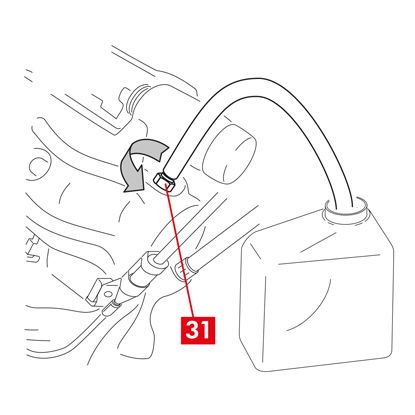
1. ต่อท่อใสเข้าที่หัวอุดระบาย (จุดที่ 31) ที่คาลิเปอร์ ปลายสายให้ต่อกับภาชนะรองรับน้ำมัน
2. เปิดหัวอุดระบาย (จุดที่ 31)
3. กดซ้ำ ๆ ที่แป้นเบรกของรถจนกว่าน้ำมันเบรกจะเริ่มไหลออกจากหัวอุดระบาย
4. กดที่แป้นเหยียบให้ชิดกับหัวอุดระบาย ปล่อยแป้นเหยียบสักครู่ จากนั้นทวนซ้ำขั้นตอนจนกว่าน้ำมันจะไม่มีฟองอากาศออกมาและจนกว่าจะเกิดแรงต้านตามปกติและระยะเคลื่อนของแป้นเบรกกลับเข้าที่
5. ขันแน่นหัวอุดระบาย (จุดที่ 31) โดยใช้แรงบิดขันแน่นตามที่ระบุในตาราง:
| หัวอุดระบาย | M6x1 | M8x1,25 | M10x1 | M12x1 |
| แรงบิดขันแน่น | 5÷7 Nm | 7÷10 Nm | 17÷20 Nm | 18÷22 Nm |
6. ถอดท่อใส
7. ทวนซ้ำขั้นตอนการไล่ระบบสำหรับหัวอุดระบายอื่น ๆ
8. หลังจากไล่ระบบเสร็จสิ้น ให้ดึงลูกสูบกลับภายในคาลิเปอร์ให้สุดโดยใช้เครื่องมือที่เหมาะสม (เช่น เครื่องถ่าง) จากนั้นเติมน้ำมันตามที่ผู้ผลิตแนะนำ
9. ปิดฝาปิดถังน้ำมันเบรก
10. ขณะเครื่องยนต์ทำงาน ให้ใช้แรงกดไปที่แป้นเบรกของรถให้หนักแน่นและตรวจสอบว่าไม่มีน้ำมันรั่วไหลจากคาลิเปอร์หรือไม่มีการสูญเสียแรงดันอย่างผิดปกติในวงจร และไฟเบรกหลังติดสว่าง
อันตราย! หากมีน้ำมันรั่วไหลจากคาลิเปอร์ ให้ทวนซ้ำขั้นตอนทั้งหมดที่ระบุในเอกสารนี้เพื่อระบุสาเหตุและทำการแก้ไขปัญหา
สำหรับคาลิเปอร์ที่มีเบรกจอด
- ประกอบตัวบ่งชี้สถานะการสึกหรอกลับเข้าที่ (ถ้ามี) บริเวณขั้วต่อที่รถ ยึดโดยใช้แรงกดเล็กน้อยที่แผ่นชิมบนคาลิเปอร์ แล้วยึดส่วนต่อพ่วงต่าง ๆ เข้าที่แชสซี
- ปรับแรงตึงที่ถูกต้องที่สายควบคุม
- โยกเบรกจอดซ้ำ ๆ ที่ห้องโดยสารภายในรถจนกว่าจะได้ระยะตามปกติ
สำหรับคาลิเปอร์ ECS
1. ถอดฝาครอบป้องกั (ถ้ามี) จากนั้นต่อสายจ่ายไฟ (จุดที่ 2)
2. ทำการรีเซ็ต (ตรวจสอบงานประกอบ)
3. ในกรณีที่จำเป็น ให้รีเซ็ตตัวนับจำนวน (รีเซ็ตตัวนับจำนวนภายใน) ตามที่ผู้ผลิตรถระบุ
4. ทำการรันอินแผ่นเบรกตามที่ผู้ผลิตรถกำหนด
5. ปลดอุปกรณ์วินิจฉัยปัญหา (On Board Diagnosis – OBD)
สำหรับคาลิเปอร์ทุกประเภท
1. ประกอบล้อกลับเข้าที่
2. หากเป็นแผ่นเบรกใหม่ ให้ทำการรันอิน ทำตามคำแนะนำที่แจ้งมากับแผ่นเบรกอะไหล่
2. หากเป็นแผ่นเบรกใหม่ ให้ทำการรันอิน ทำตามคำแนะนำที่แจ้งมากับแผ่นเบรกอะไหล่
ข้อจำกัดในการรับประกัน
การรับประกันนี้ครอบคลุมข้อบกพร่องที่เกิดขึ้นภายในระยะเวลาสองปีนับจากที่จัดส่งสินค้า ผู้บริโภคจะต้องแจ้งให้ผู้ขายทราบข้อบกพร่องของผลิตภัณฑ์ภายในสองเดือนนับจากวันที่ทราบว่าเกิดข้อบกพร่องขึ้นและยอมรับว่าระยะเวลาภายใต้ข้อจำกัดในการขอให้มีการแก้ไขคือยี่สิบหกเดือนนับจากมีการจัดส่งสินค้า ในกรณีที่พบข้อบกพร่อง ผู้ใช้มีสิทธิ์ซ่อมแซมหรือเปลี่ยนสินค้า หรือขอลดราคาตามความเหมาะสมหรือยกเลิกสัญญาตามที่กำหนดใน art. 130 ของ Consumer Code แล้วแต่กรณี
การรับประกันนี้ถือเป็นการรับประกันโดยเด็ดขาดที่จัดให้สำหรับผลิตภัณฑ์นี้และมีผลแทนที่การรับประกันอื่น ๆ ทั้งโดยวาจาหรือที่เป็นลายลักษณ์อักษร
ในกรณีที่พบข้อบกพร่อง ผู้ใช้จะต้อง:
- แจ้งให้ผู้ผลิตและตัวแทนจำหน่ายทราบเป็นลายลักษณ์อักษรภายในหกสิบวันและมีบทลงโทษหากแจ้งข้อมูลที่เป็นเท็จ นอกจากนี้ผู้ใช้จะต้องระบุรายละเอียดข้อบกพร่องที่พบเกี่ยวกับผลิตภัณฑ์หรือชิ้นส่วนใด ๆ ที่ส่งคืน รวมทั้งแสดงหลักฐานการจัดซื้อในฐานะผู้ใช้รายแรกระบุรายละเอียดเกี่ยวกับผลิตภัณฑ์และวันที่จัดซื้อ (ไม่ว่าจะเป็นการซื้อปลีกหรือจำหน่ายโดยตัวแทนจำหน่ายเป็นส่วนหนึ่งของการติดตั้งผลิตภัณฑ์ใด ๆ)
- ส่งผลิตภัณฑ์ที่สงสัยว่ามีข้อบกพร่องไปยัง Brembo S.p.A. ที่สำนักงานใหญ่ Brembo 25 -24035 Curno (BG) - Italy หรือเครือข่ายจัดจำหน่าย
การรับประกันไม่ครอบคลุมสำหรับ:
- ความเสียหายกับผลิตภัณฑ์ที่เกิดขึ้นทั้งหมดหรือบางส่วนจากการใช้งานที่ไม่ถูกต้อง อุบัติเหตุ เพลิงไหม้ การกัดกร่อนจากสารเคมี การใช้นอกเหนือจากวัตถุประสงค์ที่ระบุ การใช้งานที่ไม่ถูกต้อง การใช้งานผิดรุ่นจากที่ระบุไว้ การติดตั้งที่ไม่ถูกต้อง การติดตั้งที่ไม่เป็นไปตามที่ผู้ผลิตระบุ หรือการขาดการดูแลรักษาผลิตภัณฑ์ตามที่ผู้ผลิตระบุไว้ในชุดคำแนะนำ
- ข้อร้องเรียนที่เกี่ยวข้องกับความสบาย เสียงรบกวน การสั่นสะเทือนหรือการขับขี่ที่กระแทกรุนแรง
ผลิตภัณฑ์ได้รับการออกแบบและผลิตสำหรับรถเฉพาะรุ่นและตามการใช้งานที่ระบุในแคตาล็อกของ Brembo และ/หรือที่ระบุโดยตัวแทนจำหน่ายของ Brembo ซึ่งสามารถเข้าไปดูได้จากเว็บไซต์ของ Brembo (www.brembo.com) ใช้ผลิตภัณฑ์ตามที่กฎหมายที่มีผลบังคับใช้กำหนดในมลรัฐและ/หรือในประเทศที่รถที่ติดตั้งกับผลิตภัณฑ์ตั้งอยู่ รวมทั้งปฏิบัติตามข้อบังคับของทางหลวงและขออนุญาตตามขั้นตอนตามที่กำหนดภายในมลรัฐและ/หรือภายในประเทศ
สำหรับผลิตภัณฑ์ที่จำหน่ายในรัฐสมาชิกของสหภาพยุโรป ข้อจำกัดในการรับประกันเหล่านี้ให้เป็นไปตามเงื่อนไขของ Directive 85/374/EEC ของ Council ลงวันที่ 25 กรกฎาคม 1985
สำหรับผลิตภัณฑ์ที่จำหน่ายในสหรัฐฯ ข้อจำกัดการรับประกันเหล่านี้ให้เป็นไปตามกฎหมายของรัฐบาลกลางหรือมลรัฐที่เกี่ยวข้อง
ข้อมูลทั่วไปและข้อมูลด้านความปลอดภัย
ผลิตภัณฑ์จาก Brembo ได้รับการออกแบบมาให้เป็นไปตามมาตรฐานด้านความปลอดภัยที่เกี่ยวข้องทั้งหมด ผลิตภัณฑ์ไม่ได้มีไว้สำหรับใช้นอกเหนือจากวัตถุประสงค์ที่ระบุตามที่ออกแบบและผลิตมา การใช้งานเพื่อวัตถุประสงค์อื่น หรือการดัดแปลงและแก้ไขใด ๆ อาจทำให้ประสิทธิภาพของผลิตภัณฑ์ลดลงและทำให้เกิดความไม่ปลอดภัย
การดัดแปลงหรือใช้งานอย่างไม่ถูกต้องอาจทำให้เสียสิทธิ์การรับประเภทแบบจำกัดเงื่อนไข และอาจทำให้บุคคลที่ใช้ผลิตภัณฑ์ต้องรับผิดชอบต่อการบาดเจ็บหรือความเสียหายต่อทรัพย์สินของบุคคลอื่น
สำหรับชุดคำแนะนำนี้ ข้อความ "อันตราย!" ใช้ระบุขั้นตอนที่หากไม่ปฏิบัติตามจะมีโอกาสสูงที่จะทำให้เกิดการบาดเจ็บรุนแรงหรือการเสียชีวิต “ระวัง”” หมายถึงกระบวนการที่หากไม่ปฏิบัติตามอาจทำให้ได้รับบาดเจ็บ ส่วน “คำเตือน!” หมายถึงหากไม่ปฏิบัติตามกระบวนการที่กำหนด อาจทำให้เกิดความเสียหายต่อรถ
อันตราย!
ก่อนเริ่มการเปลี่ยนชิ้นส่วน ชิ้นส่วนอะไหล่จะต้องเหมาะสมกับยี่ห้อและรุ่นของรถ ผลิตภัณฑ์นี้มีความจำเป็นต่อความปลอดภัยของรถที่มีการติดตั้งและผลิตสำหรับติดตั้งโดยช่างผู้เชี่ยวชาญที่ผ่านการฝึกอบรมและ/หรือมีประสบการณ์ในการติดตั้งและใช้งานผลิตภัณฑ์เท่านั้น
ผู้ติดตั้งจะต้องมีเครื่องมือที่เหมาะสมในการปฏิบัติงาน และมีความรู้และประสบการณ์เกี่ยวกับงานซ่อม การติดตั้งที่ไม่เหมาะสมหรือไม่ถูกต้อง ไม่ว่าจะเนื่องจากความบกพร่องในการปฏิบัติตามคำนะนำนี้อย่างครบถ้วนหรือเนื่องจากสาเหตุอื่นใด อาจส่งผลให้สิทธิ์สิทธิ์การรับประกันแบบจำกัดเงื่อนไขและทำให้ผู้ติดตั้งต้องรับผิดต่อการบาดเจ็บหรือความเสียหายต่อทรัพย์สินที่เกิดขึ้น Brembo จะไม่รับผิดชอบใด ๆ ต่อความเสียหายหรือการบาดเจ็บที่เกิดขึ้นกับหรือโดยบุคคลที่ใช้รถที่มีการติดตั้งผลิตภัณฑ์เปลี่ยนแทนอย่างไม่ถูกต้อง
ผลิตภัณฑ์ใช้แล้วที่เปลี่ยนแทนด้วยผลิตภัณฑ์นี้จะต้องไม่นำไปติดตั้งกับผลิตภัณฑ์อื่น อาจทำให้เกิดความเสียหายต่อทรัพย์สิน การบาดเจ็บหรือการเสียชีวิตได้
ตรวจสอบระดับน้ำมันเบรกในถังว่าอยู่ระหว่างขีดล่างและขีดบนตามที่แจ้งไว้ที่ถังน้ำมัน ระดับน้ำมันที่ไม่เหมาะสมอาจทำให้น้ำมันเบรกรั่วไหลหรือประสิทธิภาพในการเบรกลดลง น้ำมันเบรกที่มากหรือน้อยเกินไปในถังพักอาจทำให้เบรกทำงานไม่ถูกต้อง และเกิดการบาดเจ็บหรือเสียชีวิตได้
ระวัง!
ทิ้งชิ้นส่วนที่เปลี่ยนตามที่กฎหมายกำหนด
หลีกเลี่ยงการฟาดและ/หรือทำให้ผลิตภัณฑ์ได้รับความเสียหาย รวมไปถึงชิ้นส่วนและส่วนประกอบต่าง ๆ เนื่องจากจะส่งผลต่อประสิทธิภาพและทำให้การทำงานผิดพลาดได้ ในกรณีที่จำเป็น ให้เปลี่ยนชิ้นส่วนหรือส่วนประกอบที่พบความเสียหาย เพื่อป้องกันการบาดเจ็บ ขอแนะนำให้ปฏิบัติตามคำแนะนำต่อไปนี้
- ใช้อุปกรณ์ที่เหมาะสมเพื่อป้องกันการสูดดมฝุ่นที่เกิดขึ้นระหว่างการทำความสะอาดชิ้นส่วน
- สวมถุงมือทุกครั้งระหว่างถอดและประกอบชิ้นส่วนที่มีขอบคม
- อย่าให้ผิวสัมผัสโดยตรงกับวัสดุเสียดทานของแผ่นเบรกและคันขาเบรกเนื่องจากอาจทำให้ถูกครูดได้
- อย่าสอดมือเข้าไปที่ฐานของแผ่นเบรกขณะถอดลูกสูบคาลิเปอร์โดยใช้ลมอัด เนื่องจากอาจทำให้มือถูกอัดกระแทกได้
- หลีกเลี่ยงการสัมผัสโดยตรงกับน้ำมันเบรก เนื่องจากอาจทำให้เกิดการระคายเคืองที่ผิวหนังและดวงตา ในกรณีที่สัมผัสโดนโดยไม่ได้ตั้งใจ ให้ทำความสะอาดให้หมดตามคำแนะนำของผู้ผลิตรถหรือน้ำมันเบรก
- อย่าให้ส่วนประกอบทางไฟฟ้าได้รับประจุไฟฟ้าสถิตหรือการกระแทกเนื่องจากชิ้นส่วนพลาสติกอาจเสียหายได้
- ปกป้องส่วนประกอบทางไฟฟ้าที่ถอดแยกออกมาจากความชื้น
- การเชื่อมต่อหน้าสัมผัสทางไฟฟ้าจะต้องเป็นไปอย่างถูกต้อง และตรวจสอบว่าไฟเตือนติดสว่างหรือไม่ หากไม่ติดสว่าง ไฟเตือนที่ไม่ทำงานอาจทำให้ประสิทธิภาพของเบรกลดลงหรือการส่งสัญญาณเกี่ยวกับเบรกล้มเหลว
- หลีกเลี่ยงการสัมผัสของจาระบีและผลิตภัณฑ์หล่อลื่นอื่น ๆ กับพื้นผิวสำหรับเบรกที่จานเบรก ดรัม แผ่นเบรกและคันขาเบรก เนื่องจากอาจส่งผลต่อประสิทธิภาพของระบบเบรกและทำให้เกิดความเสียหายอย่างรุนแรง
- อย่าใช้เครื่องมือที่แหลมคมเพื่อประกอบชิ้นส่วนยางเนื่องจากอาจทำให้เกิดความเสียหายได้ ชิ้นส่วนที่เสียหายจะต้องเปลี่ยนใหม่
การรับประกัน
เรารับประกันผลิตภัณฑ์ว่าผ่านเงื่อนไขทางเทคนิคของผู้ผลิตและปราศจากข้อบกพร่องของวัสดุและมาตรฐานการผลิต การรับประกันนี้จำกัดระยะเวลาสองปีจากวันที่จัดซื้อหรือนานกว่านี้ตามที่กฎหมายกำหนด การรับประกันนี้จำกัดระยะเวลาสองปีจากวันที่จัดซื้อหรือนานกว่านี้ตามที่กฎหมายกำหนด ในกรณีที่พบข้อบกพร่อง ให้แจ้งภายใน 60 วันหลังจากทราบและไม่เกินสองปีนับจากวันที่จัดซื้อ ในกรณีที่ยืนยันพบว่ามีข้อบกพร่องจริงและอยู่ในเงื่อนไขการรับประกัน ผลิตภัณฑ์จะถูกจัดซ่อมหรือเปลี่ยนใหม่หรือปรับแก้ทั้งชิ้น การรับประกันนี้ไม่ครอบคลุมความเสียหายที่เกิดขึ้น (ทั้งหมดหรือบางส่วน) จากการใช้งานผิดวัตถุประสงค์ เพลิงไหม้ การกัดกร่อนทางเคมี การใช้งานที่ขัดต่อกฎหมายหรือวัตถุประสงค์อื่นใดนอกเหนือจากที่ระบุไว้ การใช้กับรถรุ่นอื่นที่ไม่ได้ระบุ การติดตั้งที่ไม่ถูต้องหรือไม่เป็นไปตามที่ผู้ผลิตแจ้ง การไม่ดูแลรักษาผลิตภัณฑ์ตามที่ผู้ผลิตแจ้งไว้ในคำแนะนำที่จัดไว้ให้
มีอะไรที่คุณต้องการสอบถามหรือไม่
ติดต่อทีมงานบริการด้านเทคนิคจาก Brembo ช่างเทคนิคของเราจะติดต่อกลับไปหาคุณโดยเร็วที่สุด!